In industrial automation and heavy machinery, precise control of hydraulic cylinder stroke is paramount for safety, efficiency, and process repeatability. Proximity switch sensors have become the cornerstone technology for achieving this control, offering non-contact detection of the piston rod position. Unlike mechanical limit switches, these electronic sensors provide high reliability, fast response times, and exceptional durability in harsh environments typical of hydraulic systems. This article delves into the operational principles, selection criteria, installation methodologies, and maintenance best practices for proximity sensors in cylinder stroke applications.
Proximity sensors function by generating an electromagnetic field. When a metallic target—typically the piston rod itself or a flag mounted on it—enters this field, it induces eddy currents. The sensor detects this change and triggers a solid-state switching signal. For hydraulic cylinders, inductive proximity sensors are predominantly used due to their compatibility with ferrous metals. Key specifications include sensing distance, switching frequency, housing material, and environmental protection ratings (IP and NEMA). The sensing distance must be carefully selected to account for mechanical tolerances and thermal expansion of the cylinder without risking false triggers. Cylinder-mounted sensors often feature robust, threaded metal housings (e.g., M8, M12, M18) with high IP67/IP69K ratings to withstand hydraulic fluid exposure, pressure washdowns, and vibration.
Selecting the optimal sensor requires a thorough analysis of the application. Factors include cylinder stroke length, required positioning accuracy, operating speed (cycle time), and the ambient conditions. For long-stroke cylinders, multiple sensors may be installed along the cylinder barrel to detect intermediate positions. In contrast, compact cylinders might utilize a single sensor at each end-of-stroke position. The choice between normally open (NO) and normally closed (NC) output configurations depends on the fail-safe requirements of the control system. Furthermore, the electrical characteristics—such as DC (2-wire or 3-wire) or AC supply voltage, and PNP vs. NPN output—must be compatible with the existing programmable logic controller (PLC) or machine interface.
Installation is a critical phase that directly impacts sensor performance and longevity. Proper alignment between the sensor's sensing face and the target is essential. The target should be of sufficient size and material (mild steel is standard) to ensure consistent detection. For sensing the piston rod directly, the sensing distance may be reduced; manufacturers provide derating factors. Sensors should be mounted securely using appropriate brackets to minimize stress on the housing. Conduit or flexible cable glands must be used to protect the electrical connection from moisture and strain. It is crucial to maintain a safe distance from welding equipment or high-current cables to prevent electromagnetic interference.
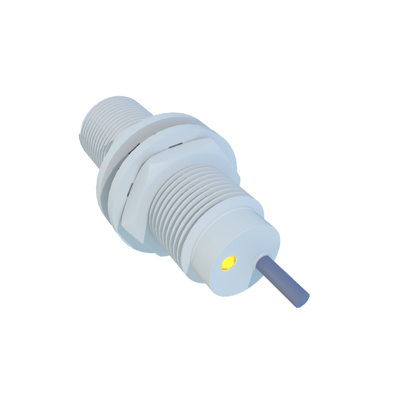
Integration with the machine control system is straightforward. The sensor's output wire is connected to a digital input module on the PLC. The ladder logic or control program is then configured to interpret the sensor signal, initiating actions such as reversing solenoid valve direction, starting a timer, or triggering the next sequence in an automated cycle. Diagnostic LEDs integrated into most modern sensors provide immediate visual feedback on power status and switching state, greatly aiding in commissioning and troubleshooting.
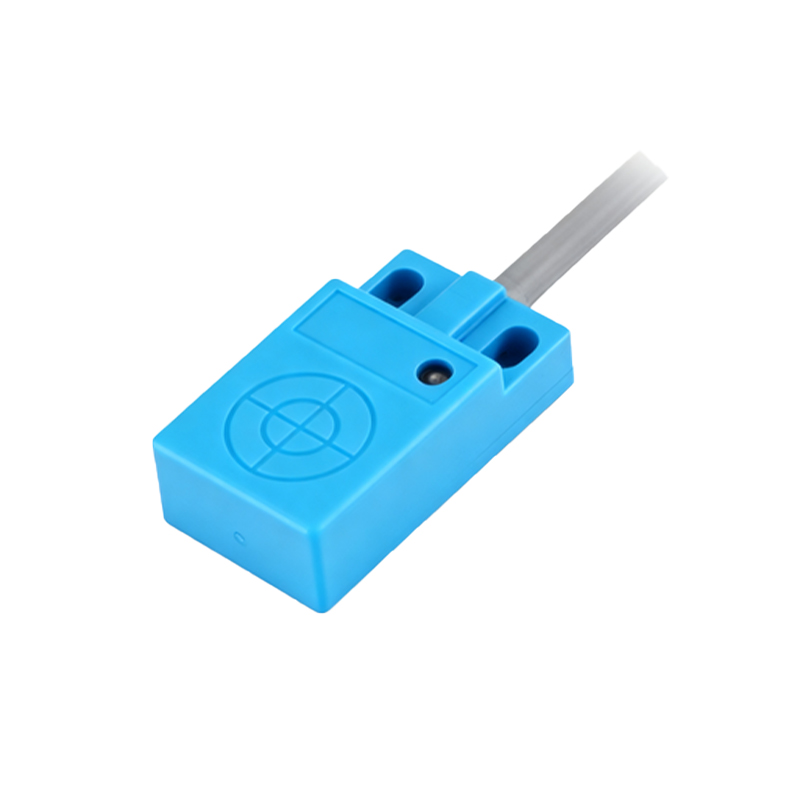
Maintenance, though minimal, is necessary for sustained reliability. Regular inspections should check for physical damage, loose mounting hardware, and integrity of cable connections. The sensor face must be kept clean of accumulated metal chips, dirt, or hardened hydraulic fluid, which can attenuate the sensing field. In extremely demanding environments, sensors with PTFE-coated faces resist sticky deposits more effectively. A periodic functional test, by manually cycling the cylinder and verifying the control system response, can preempt unexpected downtime.
The evolution of sensing technology continues to benefit cylinder control. Analog output proximity sensors provide continuous position feedback, enabling proportional control rather than simple limit switching. IO-Link enabled sensors offer advanced diagnostics, parameterization via the control network, and detailed status information like operating hours or temperature warnings, paving the way for predictive maintenance strategies.
In conclusion, the correct application of proximity switch sensors transforms a basic hydraulic cylinder into a precisely controlled actuator. By adhering to rigorous selection, precise installation, and proactive maintenance protocols, engineers can ensure optimal machine performance, enhanced safety, and maximized operational uptime in any industrial setting.