In the realm of industrial automation and machine safety, metal proximity sensors are indispensable components. Their primary function is to detect the presence or absence of metallic objects without physical contact, relying on electromagnetic fields. Understanding their schematic diagrams is crucial for engineers and technicians involved in system design, installation, troubleshooting, and maintenance. This article delves into the typical schematic representations of common metal proximity sensor types, namely inductive and capacitive variants, explaining the symbols, wiring configurations, and operational principles depicted.
The core of an inductive proximity sensor schematic revolves around an oscillator circuit, a demodulator, a Schmitt trigger, and an output switching stage. The symbol for the sensor itself is often a simple rectangle or a diamond shape with a wave symbol in front, indicating the sensing face. Internally, the oscillator generates a high-frequency electromagnetic field at the sensing face. When a metallic object enters this field, eddy currents are induced in the target, causing a change in the oscillator's amplitude. This change is detected by the demodulator, which then signals the trigger circuit to activate the output switch. In schematic diagrams, you will typically see terminals labeled as: +V (brown wire, typically 10-30V DC), -V or 0V (blue wire), and the output signal (black wire for NPN/PNP switching). The output is often represented by a transistor symbol (NPN or PNP) within the sensor block. A two-wire AC sensor schematic, conversely, shows the sensor in series with the load, functioning like a switch directly on the AC line.
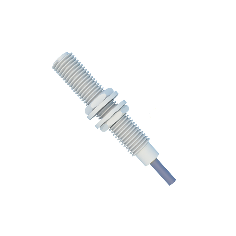
Wiring diagrams are a practical subset of schematics. A standard 3-wire DC sensor schematic will clearly show the connection to a DC power supply and the load (e.g., a PLC input, relay coil). For an NPN (sinking) output sensor, the black wire connects the load to the sensor, which then sinks the current to 0V. The schematic depicts the load between +V and the sensor's output. For a PNP (sourcing) output, the sensor provides the positive voltage to the load, which is then connected to 0V. It is paramount to note these differences in the schematic to avoid incorrect wiring that could lead to malfunction or damage. Many schematics also include protective components like reverse polarity protection diodes, short-circuit protection, and status LEDs, represented by their standard electronic symbols.
Capacitive proximity sensors, capable of detecting both metallic and non-metallic materials, have a slightly different schematic emphasis. Their principle is based on capacitance change. The schematic often highlights the internal electrode (sensing face) forming one plate of a capacitor, with the target object acting as the other plate. The oscillator circuit is tuned to respond to changes in this capacitance. The wiring symbols and terminal designations are usually identical to their inductive counterparts (brown, blue, black), but the internal block diagram within the schematic will specify the capacitive sensing method. This distinction is key when selecting a sensor from a schematic or datasheet for a specific application, such as detecting liquid levels through a non-metallic container wall.
Beyond basic connections, advanced sensor schematics may include symbols for additional features. These can include: a separate output for a normally closed (NC) function, timing functions (on-delay, off-delay) represented by clock symbols, analog output representations (e.g., 0-10V or 4-20mA signal paths), and IO-Link or AS-Interface communication interfaces with dedicated data line symbols. Understanding these elements on a schematic allows for the implementation of more complex logic and integration into sophisticated control networks.
In conclusion, a metal proximity sensor schematic is not merely a wiring guide; it is a functional map of the device's electronic soul. Proficiency in reading these diagrams enables precise integration into control panels, ensures compatibility with programmable logic controllers (PLCs), and expedites fault diagnosis. Whether it's a simple 3-wire DC inductive sensor or a complex multi-function capacitive unit with communication capabilities, the schematic provides the universal language for deployment. Always cross-reference the schematic with the manufacturer's datasheet for specific details like sensing ranges, housing materials, and environmental ratings to ensure optimal performance and safety in the intended industrial application.