Laser displacement sensors are critical tools in modern industrial automation, quality control, and R&D applications. Their non-contact measurement capability allows for high-speed, high-accuracy detection of position, thickness, vibration, and profile on a wide variety of target materials. Proper operation is key to leveraging their full potential. This guide outlines the fundamental steps and best practices for operating a laser displacement sensor effectively.
1. Pre-Operation Setup and Considerations
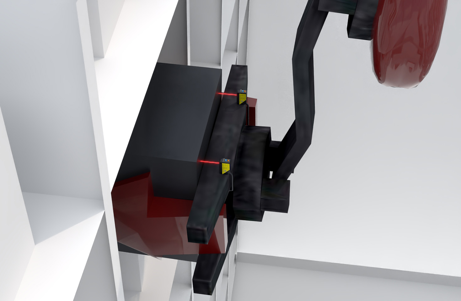
Before powering on the sensor, a thorough setup is essential. First, select the appropriate sensor model for your application. Key selection criteria include measurement range, resolution, spot size, sampling speed, and the material/surface condition of the target (e.g., shiny, dark, transparent). Ensure the operating environment is within the sensor's specified temperature, humidity, and illumination limits. Avoid areas with excessive dust, oil mist, or strong ambient light that could interfere with the laser beam. Securely mount the sensor using a stable bracket or fixture to minimize vibration. The sensor must be positioned so that the laser beam is perpendicular to the target surface within the specified allowable tilt angle to prevent cosine error.
2. Electrical Connection and Power-Up
Connect the sensor to a stable power supply as per the manufacturer's manual, typically 12-24V DC. Pay strict attention to polarity. Next, connect the output cables. Common output types include analog (4-20mA, 0-10V), digital (RS-485, Ethernet), and discrete (NPN/PNP open collector). Ensure the wiring matches your controller (PLC, data acquisition system) specifications. Once connections are verified, apply power. Most sensors have indicator LEDs that show power status and operational mode.
3. Initial Configuration and Parameter Setting
After power-up, configuration is necessary. Many modern sensors offer multiple configuration methods:
* Teach-in/Setting Mode: Using built-in buttons or a teach wire. This often involves placing a reference target at the desired "zero" point and pressing a button to set that position, then moving it to a second known point to set the measurement span or range.
* Software Configuration: Using dedicated PC software provided by the manufacturer. This offers the most comprehensive control. Connect via USB or Ethernet. The software allows you to set the measurement window (allowing only data within a specific distance range to be valid), filtering parameters (to smooth out noise from surface roughness or vibration), output scaling, and sampling rate. For challenging surfaces, you may need to adjust the laser power or receiver sensitivity.
* Controller Programming: Parameters can sometimes be set via commands sent through the digital communication protocol.
4. Alignment and Calibration
Precise optical alignment is crucial. Use the sensor's alignment aid (often a visible red pilot laser or through-the-lens sight). Fine-tune the sensor's position so the laser spot is stable and focused on the exact measurement point. For profile scanning, ensure the sensor is traversed linearly relative to the target. Calibration verifies accuracy. Use a high-precision calibration standard (e.g., gauge blocks, a micrometer stage) at multiple points within the measurement range. Compare the sensor's readout to the known standard values. If a deviation exists, use the software to perform a linearity correction or input an offset/gain value to match the output to the physical displacement.
5. Operational Monitoring and Data Acquisition
During live operation, monitor the stability of the measurement value. Utilize the sensor's built-in monitoring functions if available, such as Hi/Lo limit alarms or window comparators, which can trigger an output when a measurement falls outside preset boundaries. For dynamic measurements (e.g., vibration), ensure the sensor's response frequency is sufficiently higher than the target's vibration frequency. Capture data using your connected DAQ system or PLC, applying any necessary scaling in the receiving software to convert the voltage or current signal back into engineering units (micrometers or millimeters).
6. Troubleshooting Common Issues
* Unstable Readings: Caused by vibration, target surface texture (too rough or too shiny), or electrical noise. Improve mounting stability, adjust filtering, or use a sensor with a diffuse reflection model for rough surfaces. For shiny surfaces, use a model with a polarized filter or a triangulation sensor with a sharper acceptance angle. Ensure proper grounding and use shielded cables.
* Measurement Error or Out-of-Range: Verify the target is within the measurable range and the spot is correctly positioned. Check for obstructions in the beam path. Confirm the measurement window settings are correct.
* No Output: Verify power and wiring connections. Check the indicator LED status. Ensure the target is reflecting sufficient light back to the receiver.
7. Safety and Maintenance
Laser displacement sensors typically use Class 2 visible red lasers, which are eye-safe for momentary exposure but should never be stared into directly. Avoid pointing the beam at reflective surfaces that could redirect it. Keep the front lens clean using only recommended materials (air blower, lens tissue with appropriate cleaner). Periodically re-check calibration, especially if the operating environment changes significantly or after physical shock.
By following these operational guidelines, engineers and technicians can ensure their laser displacement sensors deliver reliable, repeatable, and accurate data, forming a cornerstone of precise industrial measurement and control systems. Always consult the specific manual for your sensor model, as procedures and features can vary.