In industrial automation and machinery design, the reliable installation of proximity switch sensors is a critical factor that directly impacts system performance, safety, and maintenance intervals. Among various mounting methods, screw fastening remains the most prevalent and trusted technique for securing these vital sensing components. This article delves into the engineering principles and practical methodologies for optimal screw fastening of proximity switch sensors, ensuring long-term operational integrity.
The primary function of a proximity switch sensor is to detect the presence or absence of a target object without physical contact, typically through inductive, capacitive, or magnetic principles. Any movement, vibration, or misalignment of the sensor body can lead to false triggering, signal loss, or inconsistent detection ranges. Therefore, the fastening system must provide rigid mechanical fixation while protecting the sensor from external stresses and environmental factors.
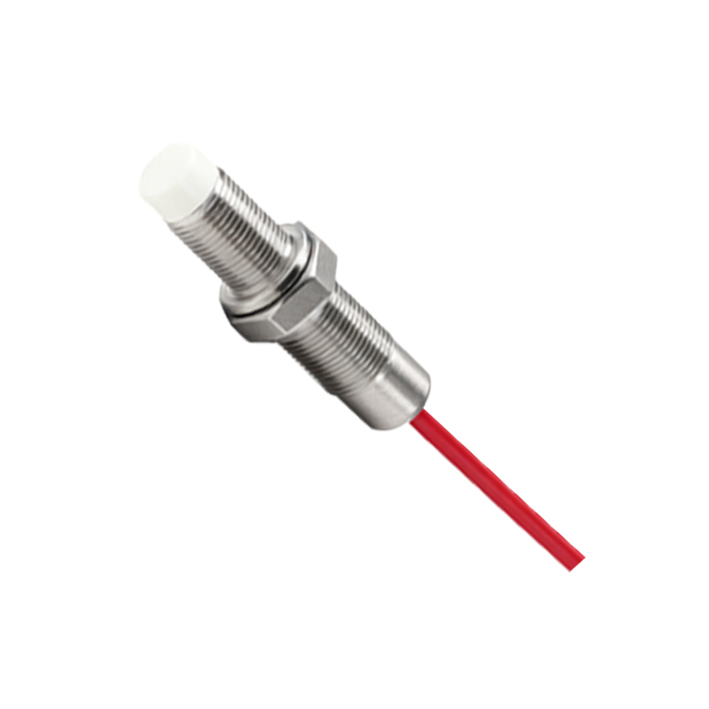
Selection of Fastening Components: The process begins with the correct selection of hardware. Most industrial proximity sensors feature a threaded barrel, commonly in M8, M12, M18, or M30 sizes. The corresponding locknut and mounting bracket must be precisely matched to this thread specification. It is imperative to use high-grade materials, typically zinc-plated steel or stainless steel (A2/A4-70 or higher), to resist corrosion, especially in washdown, outdoor, or chemically aggressive environments. The use of non-metallic or low-grade hardware is discouraged as it may succumb to vibration-induced loosening or material fatigue.
Mounting Surface Preparation: The mounting surface on the machine frame or bracket must be flat, clean, and free of burrs or paint. An uneven surface creates a pivot point, causing the sensor to tilt when the locknut is tightened. This tilt induces bending stresses on the sensor housing and can misalign the sensing face relative to the target's path. A flat, machined surface ensures uniform contact and force distribution. For added stability on thinner sheet metal, reinforcing mounting brackets or backing plates are recommended.
Torque Application and Tightening Procedure: Applying the correct torque is paramount. Under-tightening leads to loosening under vibration, while over-tightening can crush the sensor housing, damage internal electronics, strip threads, or distort the sensing field. Manufacturers provide specific installation torque values in their datasheets, which must be strictly adhered to. For a standard M12 inductive sensor, a typical installation torque ranges from 10 to 15 Nm (7 to 11 lbf-ft). A calibrated torque wrench should be used for critical applications. The recommended procedure is to hand-start the locknut, then use the wrench to apply a smooth, steady force until the specified torque is reached. Avoid impact tools, as they can generate peak forces far exceeding the sensor's rating.
Anti-Loosening Strategies: In high-vibration environments, such as on presses, conveyors, or mobile equipment, standard locknuts may gradually loosen. Engineers should employ proven anti-loosening strategies. These include the use of:
Spring washers or split lock washers: Provide a spring force that maintains nut tension.
Nylon-insert locknuts (nyloc nuts): Offer excellent vibration resistance through friction.
Double-nut (jam nut) method: Using two nuts tightened against each other.
Thread-locking adhesives: Medium-strength threadlockers (e.g., Loctite 243) can be applied to the sensor threads. Caution is advised to prevent adhesive from wicking into the sensor's internal cavity.
Sensor Alignment and Gap Setting: After secure fastening, final alignment is crucial. The sensing face must be perpendicular to the target's plane of travel, and the air gap (the distance between the sensor face and the target) must be set according to the sensor's rated operating distance, typically at 70-80% of the nominal value to account for thermal drift and mechanical tolerances. A properly tightened sensor allows for precise micro-adjustments during this alignment phase without shifting under its own weight.
Post-Installation Verification and Maintenance: Following installation, conduct a functional test by cycling the target object and monitoring the sensor's output signal with an oscilloscope or PLC input indicator. Establish a preventive maintenance schedule to periodically check the tightness of critical sensor mounts, especially after the first few hours of operation (settling period) and at regular intervals thereafter. Look for signs of corrosion, physical damage, or witness marks indicating movement.
In conclusion, the screw fastening of a proximity switch sensor is far from a mere mechanical task; it is a precision engineering practice that bridges electrical functionality and mechanical robustness. By meticulously selecting components, preparing surfaces, applying controlled torque, and implementing anti-vibration measures, engineers and technicians can ensure that these sensors deliver their promised reliability, accuracy, and longevity, forming a dependable backbone for automated industrial systems.