Laser distance measurement sensors have become indispensable tools across various industries, including manufacturing, robotics, construction, and autonomous systems. At the heart of these precise instruments lies a sophisticated electronic circuit that orchestrates the emission, reception, and interpretation of laser light. This article delves into the core circuit design principles and implementation strategies for building a reliable and accurate laser rangefinder.
The fundamental operating principle is Time-of-Flight (ToF). The circuit's primary function is to measure the time interval between emitting a laser pulse and receiving its reflection. This time, when multiplied by the speed of light and divided by two, yields the distance to the target. The circuit architecture can be broadly segmented into several key modules: the laser driver, the photodetector receiver, the timing circuit, and the signal processing unit.
The laser driver circuit is critical for generating short, high-power optical pulses. Typically, a pulsed laser diode (PLD) is used. The driver must provide a high-current, fast-rising pulse to the diode. This is often achieved using a MOSFET switch controlled by a pulse generator from a microcontroller (MCU) or a dedicated timing IC. A crucial consideration is protecting the sensitive laser diode from current spikes and reverse voltage. This is managed with fast-switching transistors, current-limiting resistors, and often a dedicated laser driver IC that ensures stable and controlled pulse characteristics, which are vital for measurement consistency.
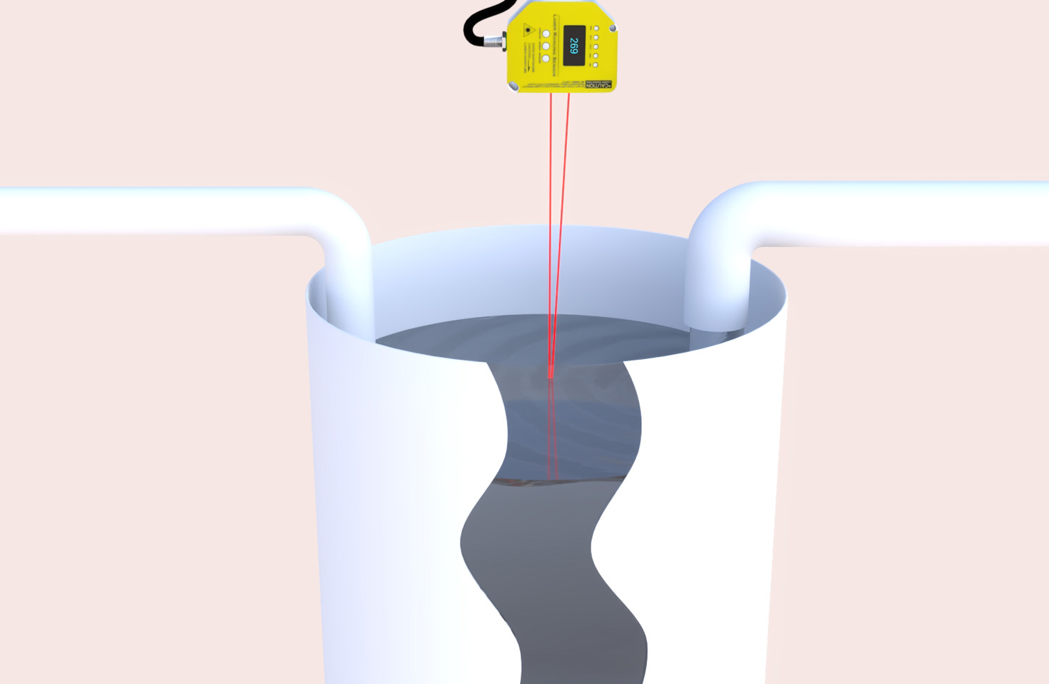
On the receiving end, the photodetector circuit awaits the faint returning signal. An avalanche photodiode (APD) or a PIN photodiode is commonly employed for its high sensitivity and speed. The photocurrent generated is extremely weak and requires immediate amplification. A transimpedance amplifier (TIA) is the first and most critical stage in the receiver chain. It converts the small photocurrent into a usable voltage signal while minimizing noise. The design of the TIA, including feedback resistor and capacitor selection, directly impacts bandwidth and signal-to-noise ratio (SNR). Following the TIA, additional gain stages and high-speed comparators are used to condition the signal into a clean digital pulse that can be processed by the timing logic.
The core of the distance calculation is the timing circuit. For high-precision measurements, direct time measurement using a high-speed counter is essential. An internal timer within a high-performance MCU or, more commonly, a dedicated Time-to-Digital Converter (TDC) IC is used. The TDC offers picosecond-level resolution, enabling millimeter or even sub-millimeter accuracy. The circuit starts this ultra-precise timer the instant the laser driver is triggered and stops it the moment the comparator detects the return pulse. This elapsed time data is then passed to the processing unit.
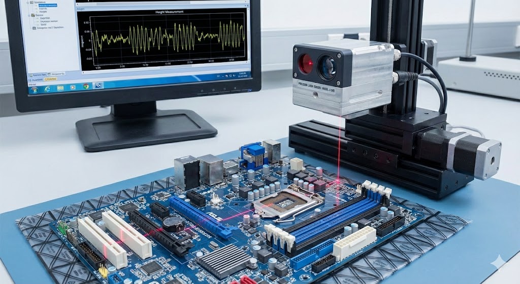
Signal processing, often handled by an MCU or FPGA, manages the overall system. It controls the pulse repetition frequency, reads the raw time data from the TDC, applies necessary calibrations (e.g., for temperature drift), and calculates the final distance. Advanced implementations use statistical methods, like taking multiple measurements and averaging, to improve accuracy and filter out noise. The processing unit also handles communication interfaces (e.g., UART, I2C, SPI) to output the distance data to a host system.
Implementation challenges are significant. Noise immunity is paramount. Careful PCB layout practices are mandatory: separating analog (receiver, TIA) and digital (MCU, TDC) grounds, using short and direct traces for high-speed signals, and employing proper decoupling capacitors. Power supply stability is also critical, as noise on the supply rails can easily degrade the sensitive analog front-end. Furthermore, ambient light, especially sunlight, can saturate the photodetector. Optical filters that match the laser's wavelength (e.g., 905nm) are used in front of the photodiode, and sometimes electronic filtering techniques are applied in the signal chain.
In conclusion, designing a laser distance sensor circuit is a multidisciplinary challenge involving optoelectronics, analog circuit design, high-speed digital timing, and embedded programming. A successful design balances performance parameters like range, accuracy, speed, and power consumption. By meticulously designing each module—from the robust laser driver and low-noise TIA to the picosecond-accurate TDC—engineers can create laser ranging systems that deliver reliable and precise measurements for the most demanding industrial applications. Continuous advancements in integrated circuits, such as single-chip ToF sensors, are simplifying design but understanding these underlying circuit principles remains fundamental for optimization and troubleshooting.