Visual inspection serves as the first line of defense in predictive maintenance for proximity sensors. A systematic external examination can reveal early signs of failure, contamination, or physical damage that might compromise sensor performance in automated systems. This guide outlines a professional visual inspection protocol for inductive, capacitive, and magnetic proximity switches commonly used in industrial environments.
Begin by ensuring the system is in a safe state, following Lockout-Tagout (LOTO) procedures before any inspection. Initial assessment should focus on the sensor's housing. Check for cracks, dents, or deformities in the metal or polymer body. Even minor cracks can allow ingress of coolant, metal chips, or conductive dust, leading to internal short circuits. Pay special attention to the sensing face, the critical front surface. Look for scratches, pitting, or buildup of foreign material like grease, paint, or metallic swarf. A contaminated sensing face can significantly reduce the rated sensing distance or cause erratic switching.
Inspect the cable entry point and the cable itself if it is integrated or connected. The cable gland or strain relief must be secure and intact. Signs of pulling, twisting, or pinching can damage internal wires. Examine the cable jacket for cuts, abrasions, or signs of chemical degradation such as cracking or discoloration. For connectors, check for bent pins, corrosion, or contamination in the mating areas.
Next, evaluate the installation. Verify the sensor is mounted securely; loose mounting can cause vibration-induced failure or alter the sensing gap. Ensure there is no excessive buildup of ferrous or non-ferrous material around the mounting area, which could affect the magnetic or electrostatic field. Check for correct alignment with the target; misalignment is a common cause of unreliable operation.
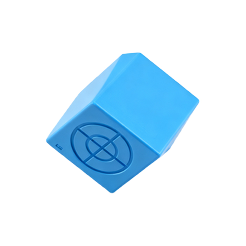
Look for environmental damage indicators. Discoloration or charring on the housing may indicate exposure to excessive heat from nearby welding or processes. Frost or condensation inside a sealed sensor's lens suggests a compromised seal and imminent failure due to moisture. For sensors in washdown areas, verify the integrity of the seal ratings (e.g., IP67, IP69K) by checking for worn O-rings or damaged sealing surfaces.
Inspect labeling and indicators. The part number, serial number, and electrical specifications should be legible. Many sensors have an LED status indicator. While powered under safe conditions, observe its behavior. A solid or blinking LED that deviates from the manufacturer's specification for normal operation can indicate internal circuit issues, even if the switch still functions.
Document all findings. Use a checklist that includes: Housing Condition, Sensing Face Cleanliness, Cable/Connector Integrity, Mounting Security, Environmental Damage, and LED Status. Comparing current observations with records from previous inspections helps track degradation over time.
A thorough visual inspection, performed regularly, is a cost-effective practice. It can prevent unplanned downtime by identifying sensors that require cleaning, recalibration, or replacement before a catastrophic failure occurs. This proactive approach extends the service life of the sensor and maintains the reliability of the entire control system. Remember, a sensor that looks faulty often is faulty. Never ignore visual cues in favor of intermittent operational performance.