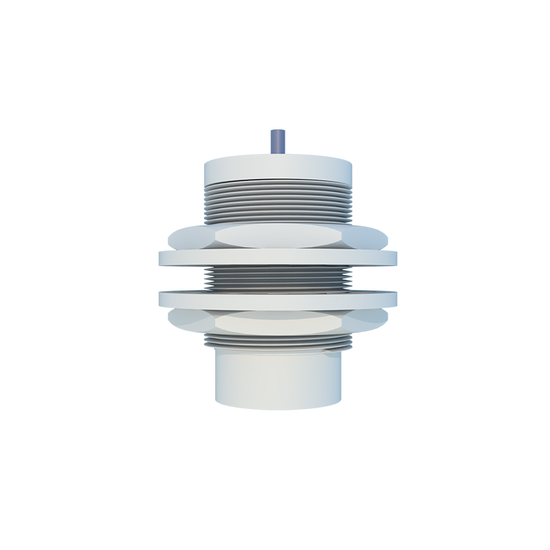
In the realm of industrial automation and electrical engineering, proximity sensors play a pivotal role in detecting the presence or absence of objects without physical contact. A fundamental aspect of integrating these devices into control systems is comprehending their electrical symbol diagrams. These symbols, standardized by organizations such as the International Electrotechnical Commission (IEC) and the National Electrical Manufacturers Association (NEMA), provide a universal language for engineers and technicians to design, interpret, and troubleshoot circuits.
The electrical symbol for a proximity sensor typically resembles a standard switch symbol but incorporates distinctive elements to denote its non-contact operation. Commonly, it features a diamond shape or a rectangle with a diagonal line, accompanied by specific markings that indicate the sensor type—inductive, capacitive, or photoelectric. For instance, an inductive proximity sensor symbol often includes a coil-like illustration or the letter "L" to represent inductance, signifying its ability to detect metallic objects through electromagnetic fields. Capacitive sensors, which can sense both metallic and non-metallic materials, may be depicted with parallel plates or a "C" notation, reflecting their reliance on capacitance changes. Photoelectric sensors, utilizing light beams for detection, might show a light emitter and receiver within the symbol, sometimes with arrow indicators for beam direction.
Understanding these symbols is crucial for reading electrical schematics and ladder diagrams in control panels. In a typical diagram, the proximity sensor symbol is connected to a power supply and a load, such as a relay or programmable logic controller (PLC) input module. The symbol's contacts—normally open (NO) or normally closed (NC)—determine the circuit behavior when an object is detected. For example, an NO contact closes upon detection, completing the circuit to activate an output device. Engineers must also consider the sensor's output configuration: NPN (sinking) or PNP (sourcing), which influences how the symbol is integrated into the wiring diagram. Misinterpreting these details can lead to installation errors, malfunctioning systems, or safety hazards.
In practice, referencing datasheets and manufacturer guidelines is essential, as symbols may vary slightly based on brand or application. For instance, some diagrams include additional annotations for shielding, sensing range, or environmental ratings. Mastery of proximity sensor symbols enhances efficiency in designing automated systems for manufacturing, packaging, and robotics, ensuring reliable object detection and seamless integration with other components like motors, valves, and HMIs. As Industry 4.0 advances, with trends toward IoT and smart factories, proficiency in these electrical symbols remains a cornerstone for engineers aiming to optimize productivity and maintainability in industrial settings.