Laser temperature sensors, often referred to as infrared (IR) thermometers or pyrometers, are indispensable tools in modern industrial processes, from metalworking and semiconductor fabrication to power generation and food processing. Their non-contact measurement capability allows for monitoring of moving objects, hazardous environments, or surfaces where physical contact is impossible or undesirable. However, achieving accurate and reliable readings requires proper calibration, setup, and ongoing troubleshooting. This guide provides a systematic approach for engineers to debug and optimize laser temperature sensor performance.
The foundation of any successful measurement begins with understanding the sensor's specifications. Key parameters include measurement range, spectral response (often defined by the sensor's wavelength, such as 8–14 µm for general purposes or specific narrow bands for glass or metals), optical resolution (distance-to-spot-size ratio), and emissivity settings. Emissivity—the efficiency with which a surface emits thermal radiation—is the most critical and common source of error. A polished metal surface may have an emissivity of 0.1, while oxidized metal or painted surfaces can approach 0.95. Always refer to published emissivity tables for the target material and, when possible, validate with a contact thermometer on a controlled sample. Many modern sensors offer adjustable emissivity settings; failing to set this correctly will lead to significant temperature deviations.
Calibration is not a one-time event but a periodic necessity to ensure traceability and accuracy. The standard method involves comparing the sensor's reading against a known reference source, typically a blackbody calibrator. The process should be conducted in a stable environment, free from drafts, excessive ambient light, or radiant heat sources that could interfere. Follow these steps: First, allow both the sensor and the blackbody source to stabilize at the operating temperature. Set the blackbody to a specific temperature within the sensor's range. Align the sensor precisely perpendicular to the blackbody's aperture, ensuring the laser spot falls entirely within the calibrated area. Record the sensor's output over several minutes. The deviation from the reference temperature indicates the sensor's error. For critical applications, perform this at multiple points across the intended operating range. Document all calibration data, including date, ambient conditions, reference values, and sensor readings, for quality records and trend analysis.
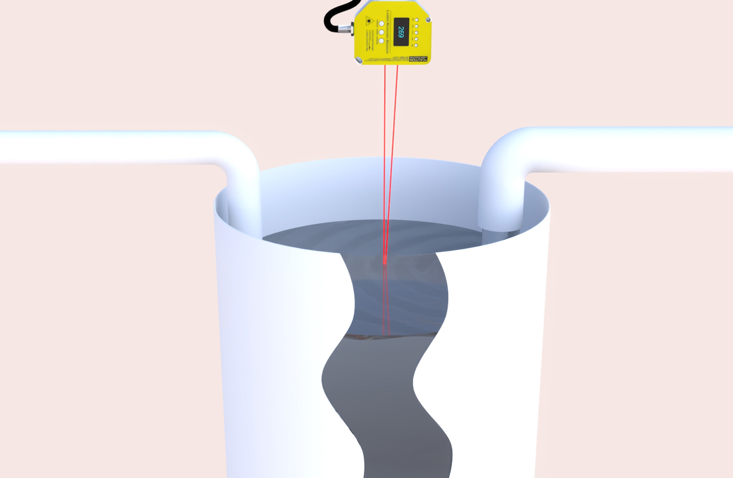
Even with proper calibration, field installations present numerous challenges. A common issue is erroneous readings due to environmental interferences. Steam, dust, smoke, or windows between the sensor and target can absorb or scatter infrared radiation, leading to lower than actual readings. Conversely, external radiant heat sources like furnaces, sunlight, or hot nearby machinery can cause falsely high readings. Mitigation strategies include using purged air or protective shrouds to keep the lens clean and the sight path clear, installing protective sapphire windows if needed (ensuring proper window transmission correction), and shielding the sensor from extraneous radiation. Always ensure the target completely fills the sensor's field of view; if the spot is only partially on the target, the sensor averages the temperature of the target and the background, causing inaccuracy.
Electrical and output signal problems are another frequent troubleshooting area. Verify the power supply voltage and current comply with the sensor's datasheet. Noise on the power line or signal output can be addressed with proper grounding, using shielded cables, and installing ferrite beads or line filters. For sensors with analog outputs (4-20 mA or 0-10 V), use a precision multimeter to check if the output corresponds correctly to the measured temperature. For digital outputs (RS-485, Modbus, Ethernet), utilize communication software to monitor the raw data and check for packet errors or configuration mismatches in baud rate and address.
Software configuration within the connected PLC, DCS, or data logger is often an overlooked culprit. Double-check scaling parameters: the engineering units and range set in the software must match the sensor's configured output range. A sensor outputting 4-20 mA for 0–1000°C will display incorrectly if the PLC is scaled for 0–500°C. Additionally, ensure any filtering or damping settings in the sensor or software are appropriate for the process dynamics; excessive damping can hide real temperature fluctuations, while insufficient filtering can cause noisy, unsteady readings.
Preventive maintenance is key to long-term reliability. Establish a regular schedule to inspect the sensor lens for contamination—clean it gently with compressed air or lens tissue and appropriate solvent. Check all mechanical mounts for stability and vibration, as misalignment can drift over time. Monitor environmental conditions around the sensor, especially ambient temperature, as extreme heat can affect electronic components. Keep a log of periodic verification checks against a known process temperature or a portable reference sensor.
In summary, debugging a laser temperature sensor is a methodical process that blends theoretical knowledge with practical investigation. Start by verifying emissivity and optical setup, then proceed to calibration against a traceable standard. Systematically eliminate environmental, electrical, and configuration interferences. By adhering to these practices, engineers can ensure their non-contact temperature measurement systems deliver the precision and reliability required for safe, efficient, and high-quality industrial operations.