In industrial automation and control systems, proximity sensors are indispensable components for non-contact detection of objects. Their reliability is paramount for ensuring seamless operations, safety, and efficiency. However, a common and often perplexing issue encountered by maintenance engineers and system integrators is sensor insensitivity—a condition where the sensor fails to detect a target within its specified sensing range or exhibits inconsistent, unreliable operation. This article delves into the root causes of this problem, provides a structured troubleshooting methodology, and offers practical solutions to restore optimal performance.
The fundamental principle behind inductive, capacitive, and ultrasonic proximity sensors involves generating an electromagnetic or acoustic field and detecting changes caused by a target's presence. Insensitivity disrupts this interaction. The symptoms are clear: missed detections, requiring objects to be impractically close for activation, or intermittent signals that lead to machine faults and production stoppages.
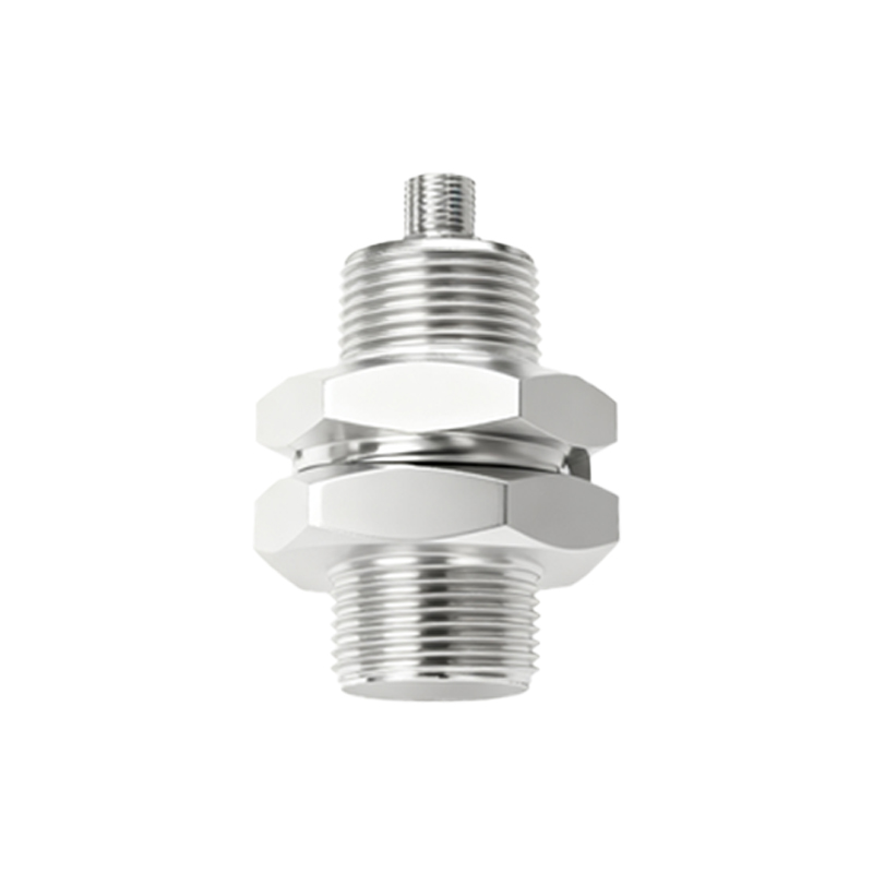
A systematic investigation into the causes of insensitivity is crucial. The primary culprits can be categorized into environmental factors, electrical issues, mechanical misalignment, and sensor degradation.
Environmental Interference: This is a leading cause. For inductive sensors, the presence of strong electromagnetic fields from nearby motors, transformers, or welding equipment can swamp the sensor's own field, causing it to ignore or misread the target. Metallic chips, dust, or conductive fluids accumulating on the sensor face can form a "false shield," effectively reducing the effective sensing distance. For capacitive sensors, changes in ambient humidity or the presence of non-target materials can alter the dielectric constant, leading to erratic behavior. Ultrasonic sensors are particularly susceptible to air turbulence, temperature gradients, and acoustic noise from other equipment.
Electrical and Installation Issues: Voltage supply problems are critical. Operating a sensor below its minimum rated voltage directly reduces its output power and sensing range. While overvoltage might not cause immediate failure, it can lead to internal component stress and premature degradation, manifesting as insensitivity over time. Electrical noise on the supply lines or the output signal line can also mask the true detection signal. Improper grounding or the lack of shielded cables in high-noise environments is a frequent oversight. Furthermore, incorrect wiring, such as mixing up PNP and NPN configurations or failing to connect the load correctly, will result in non-operation, often mistaken for insensitivity.
Mechanical and Alignment Factors: Proximity sensors have a defined sensing window or area. If the target approaches outside this optimal zone—for example, at an extreme angle or too far offset—the sensor may not trigger. Physical damage to the sensor face, such as cracks or deep scratches, can distort the emitted field. Vibration can cause temporary changes in the relative position between the sensor and the target, leading to intermittent detection. Incorrect sensor mounting, where the sensor is not flush or is recessed too deeply in a metal bracket (for inductive types), can significantly attenuate the sensing field due to the "shielding effect" of the surrounding metal.
Sensor Degradation and Selection Errors: All electronic components have a lifespan. Internal oscillator circuits can drift, and output transistors can weaken over years of service, gradually reducing the sensor's effective range. Selecting the wrong sensor type for the application is a fundamental error. Using a standard inductive sensor to detect aluminum (which has lower conductivity than steel) will result in a drastically reduced sensing distance unless a factor-corrected or "non-ferrous" specific model is used. Similarly, using a sensor with an insufficient sensing range for the required application gap will appear as persistent insensitivity.
Troubleshooting Protocol: A logical, step-by-step approach is recommended.
1. Visual Inspection: Check for physical damage, contamination on the sensing face, and secure mounting. Verify the target is appropriate (material, size).
2. Environmental Review: Identify new sources of EMI, heat, or contamination introduced since installation. Check for temperature extremes beyond the sensor's specification.
3. Electrical Verification: Use a multimeter to confirm the supply voltage is stable and within the sensor's operating range at its terminals. Monitor the output with an oscilloscope if possible to check for noise or signal integrity issues.
4. Operational Test: With the target material specified in the datasheet, gradually bring it toward the sensor face along the central axis. Measure the actual sensing distance and compare it to the rated nominal range (typically 70-80% of nominal is expected for standard conditions). Test repeatability.
5. Substitution: If possible, replace the suspect sensor with a known-good unit of the same model. If the problem is resolved, the original sensor is faulty.
Preventive Measures and Solutions: To mitigate insensitivity, adhere to the following best practices. Always select a sensor with a nominal sensing range 1.5 to 2 times the required application gap to account for tolerances and wear. Ensure