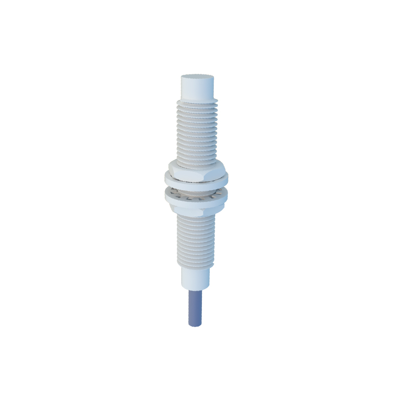
Proximity sensors are fundamental components in modern industrial automation, serving as the critical "eyes" of machinery by detecting the presence or absence of objects without physical contact. Their correct connection is paramount to system reliability, safety, and efficiency. This guide details the essential connections for inductive, capacitive, and ultrasonic proximity sensors, focusing on wiring practices, load integration, and interface with control systems.
The primary connection for any proximity sensor is to a power source. Most industrial DC sensors operate on 10-30V DC, while AC variants typically use 90-250V AC. The first step is always to consult the sensor's datasheet for voltage and current specifications. Incorrect power supply is a leading cause of premature sensor failure. For DC sensors, strict observance of polarity (brown wire to positive+, blue wire to negative-) is mandatory. AC sensors, however, are often polarity-insensitive. A stable, clean power supply is crucial; voltage spikes or electrical noise can cause erratic operation. Implementing surge protection devices and using shielded cables grounded at one end are recommended best practices.
The core function of a proximity sensor is to switch a load, most commonly the input of a Programmable Logic Controller (PLC). The sensor's output wire (usually black or white) connects to the PLC's digital input module. Two main output types exist: NPN (sinking) and PNP (sourcing). An NPN sensor switches the negative (0V) line to the load, common in Asian and European designs. A PNP sensor switches the positive voltage line to the load, prevalent in North America. Mismatching sensor output type with the PLC input circuit will result in non-operation. Many modern PLC input cards are configurable to accept either type. The load (PLC input) is then connected between the sensor's output and the opposite power supply rail, completing the circuit.
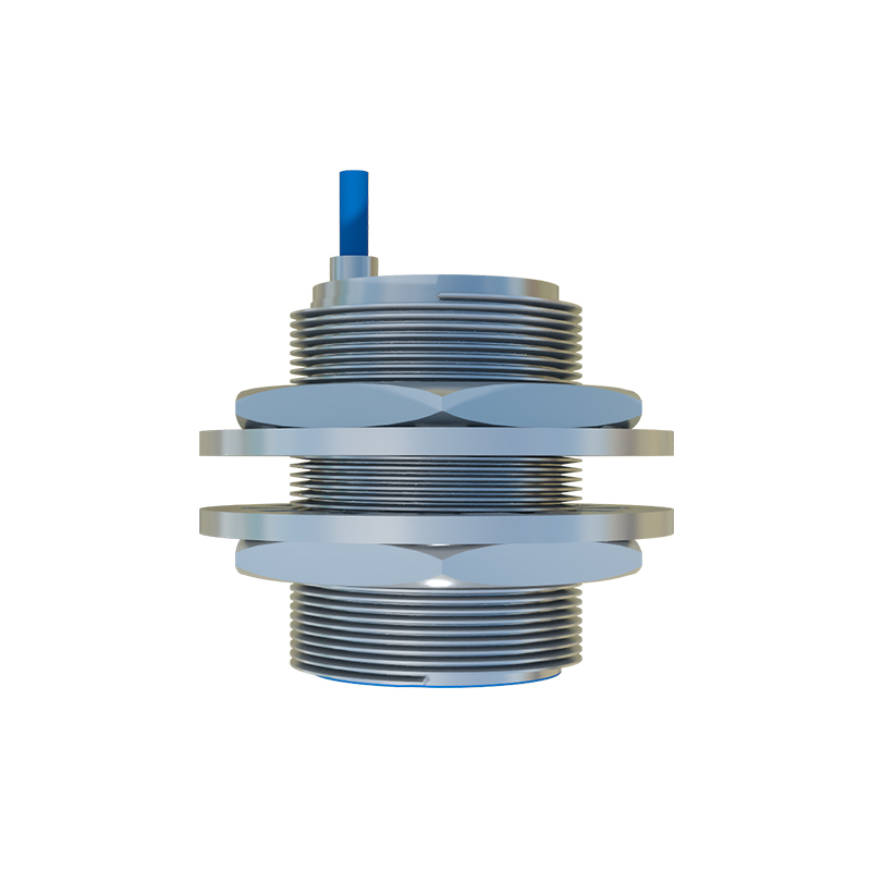
For connecting higher-power loads like relays, contactors, or solenoid valves directly, the sensor's maximum switching current and voltage ratings must not be exceeded. Typically, a sensor's solid-state output can handle 100-200mA. Connecting a load that draws more current, such as a large contactor coil, requires an intermediate relay. The sensor switches the low-current relay coil, and the relay's heavy-duty contacts then control the high-power load. This protects the sensor's delicate output transistor. Always connect a flyback or freewheeling diode across the coil of any inductive load (relay, solenoid) to suppress voltage transients that can damage the sensor.
Advanced connectivity involves networks and smart systems. Many sensors now feature IO-Link capability, a point-to-point serial communication protocol. Beyond simple on/off switching, IO-Link allows for parameter setting, process data exchange (e.g., distance value), and detailed diagnostic monitoring directly onto the controller. Connecting an IO-Link sensor requires a standard 3-wire cable (power, ground, signal) to an IO-Link master module. This digital connection simplifies wiring and enables predictive maintenance. Furthermore, sensors can connect to safety systems. Safety-rated proximity sensors, with dual redundant outputs and monitoring circuits, connect directly to safety PLCs or relays to form part of a machine's safety interlock system, such as guarding or zone monitoring.
Finally, proper physical installation and wiring management are part of the connection process. Sensors must be mounted securely, with adequate clearance from metal surfaces as specified. Cables should be routed away from high-voltage power lines and motor drives to minimize electromagnetic interference. Using conduit, cable glands, and strain relief ensures long-term connection integrity in harsh environments with vibration, moisture, and dust. A final functional test, verifying the sensor's indicator LED and the PLC input status during object detection, confirms a successful and robust connection, ensuring seamless integration into the automated process.