In industrial automation and machinery safeguarding, square proximity sensors are ubiquitous components, prized for their robust construction, non-contact detection, and reliability in harsh environments. However, an alarm triggered by a square proximity sensor can bring a production line to an abrupt halt, leading to costly downtime. This article delves into the common causes of such alarms, systematic troubleshooting methodologies, and essential maintenance practices to ensure optimal performance.
A proximity sensor alarm typically indicates that the sensor's output state does not match the expected condition for a given process. For inductive square proximity sensors, which detect metallic objects, alarms often manifest as a failure to detect a target (false negative) or continuous activation without a target present (false positive). The root causes are multifaceted.
Primary Causes of Square Proximity Sensor Alarms:
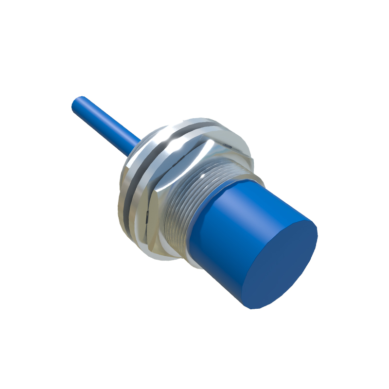
1. Misalignment and Incorrect Mounting: The sensor face must be properly aligned with the target. Even minor angular deviations or excessive gap distances beyond the sensor's rated sensing range can cause intermittent detection or complete failure. Vibration can exacerbate misalignment over time.
2. Environmental Contaminants: Industrial environments expose sensors to oil, coolant, metal chips, dust, and conductive debris. A buildup on the sensor's active face can insulate it or, in the case of metallic dust, create a false "target," leading to erratic behavior and alarms.
3. Electrical Interference and Wiring Issues: Electromagnetic interference (EMI) from nearby motors, variable frequency drives (VFDs), or welding equipment can induce noise in the sensor's signal cable or power supply, causing spurious switching. Loose connections, damaged cables, poor grounding, or incorrect wiring (e.g., mixing NPN and PNP types with the wrong controller input) are frequent culprits.
4. Sensor Degradation and Physical Damage: While rugged, sensors can suffer from cracked housings, damaged sensing faces, or internal component failure due to extreme temperature cycles, mechanical impact, or moisture ingress. The oscillator circuit, a core component, can drift or fail.
5. Incorrect Parameter Settings: Some advanced sensors feature adjustable sensing ranges, hysteresis, or output delays. Incorrect configuration for the specific application can lead to unreliable operation.
6. Target-Related Issues: The problem may not be the sensor itself. The target object's material (e.g., a non-ferrous metal with a reduced sensing factor), size (too small), or surface condition (rust, paint) can affect detection reliability.
Systematic Troubleshooting Protocol:
When an alarm activates, follow a logical diagnostic sequence:
Step 1: Visual Inspection. Power down the equipment following lockout-tagout (LOTO) procedures. Inspect the sensor for physical damage, contamination, and secure mounting. Verify the gap between the sensor and target. Check cable integrity and connection tightness.
Step 2: Environmental Assessment. Review recent changes in the environment—new machinery installed, changes in coolant type, or increased airborne particulates.
Step 3: Electrical Verification. With power restored and safety ensured, use a multimeter to check the supply voltage at the sensor terminals. It must be within the specified range (e.g., 10-30 VDC). Monitor the output signal with the target present and absent using a meter or oscilloscope to identify noise or an unstable signal.
Step 4: Sensor Substitution. The most definitive test is to temporarily replace the suspect sensor with a known-good unit of identical specifications. If the alarm clears, the original sensor is faulty. If not, the issue lies elsewhere in the wiring or control logic.
Step 5: Control Logic Check. Verify the PLC or controller's input card status and the programming logic associated with that sensor input to rule out a control system fault.
Preventive Maintenance Best Practices:
Proactive maintenance is key to minimizing alarms:
Regular Cleaning: Establish a schedule to wipe the sensor face with a clean, lint-free cloth. Use appropriate solvents if necessary, ensuring they are compatible with the sensor's housing material.
Scheduled Inspection: Periodically check mounting hardware for tightness, alignment, and gap distance. Inspect cables for abrasion or cuts.
Electrical Integrity Checks: Include sensor supply voltage and grounding checks in routine maintenance logs.
Environmental Protection: Utilize protective boots or shrouds designed for square proximity sensors in areas with heavy splash or chip generation. Ensure proper conduit seals.
Spare Parts Inventory: Keep critical sensors in stock to facilitate quick replacement and reduce downtime.
Understanding the operational principles and failure modes of square proximity sensors empowers engineers and maintenance technicians to swiftly diagnose alarms. A combination of methodical troubleshooting and disciplined preventive maintenance transforms these alarms from disruptive events into manageable, predictable aspects