Proximity sensors are fundamental components in modern industrial automation, providing non-contact detection of objects. Their performance is critically dependent on the measurement circuit that processes the sensor's output signal. This article delves into the core principles, design considerations, and practical implementation of measurement circuits for inductive, capacitive, and photoelectric proximity sensors, focusing on robustness and reliability in harsh industrial environments.
The primary function of a proximity sensor measurement circuit is to convert the physical phenomenon of detection—be it a change in inductance, capacitance, or light intensity—into a clean, stable, and interpretable electrical signal, typically a digital ON/OFF switch or an analog voltage/current proportional to distance. The circuit architecture varies significantly based on the sensor type.
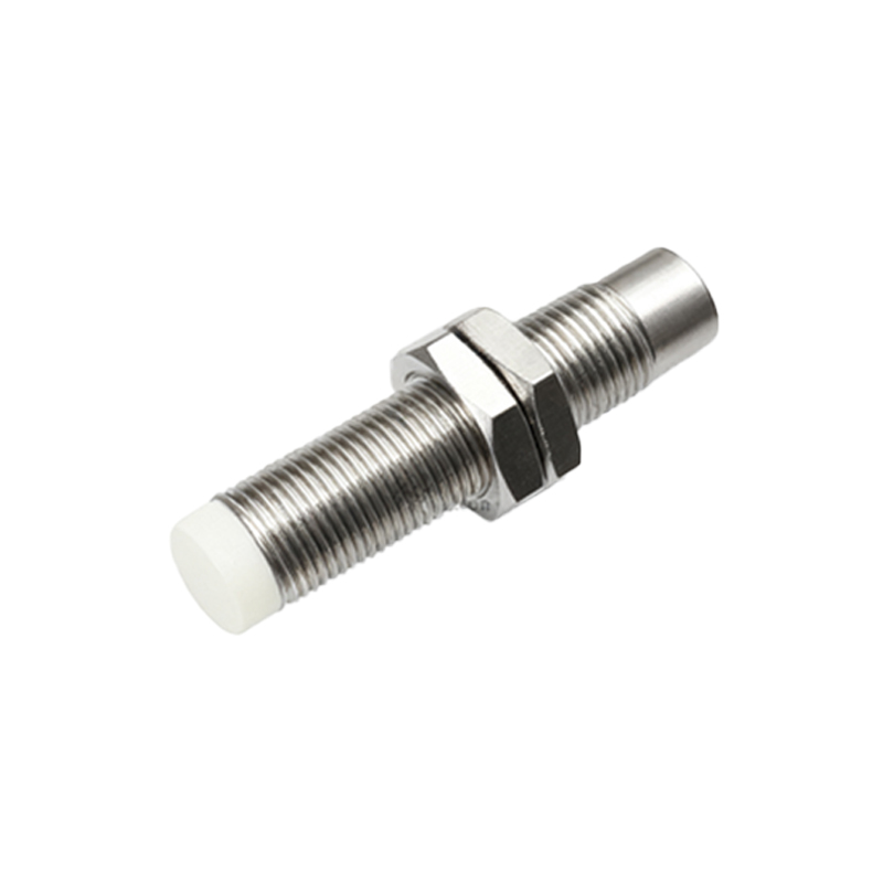
For inductive proximity sensors, which detect metallic objects, the core element is a coil forming part of an LC oscillator circuit. When a metal target enters the sensor's electromagnetic field, eddy currents are induced in the target, causing a change in the coil's inductance and a consequent shift in the oscillator's amplitude or frequency. The measurement circuit must reliably detect this shift. A common approach involves an oscillator whose signal amplitude decays when a metal object is present. This amplitude is then fed into a threshold detector (comparator) which triggers the output switch. Key design challenges include temperature compensation to offset drift in the coil's resistance, immunity to electromagnetic interference (EMI) from nearby motors or drives, and ensuring a stable oscillation across the operating voltage range. Shielding and proper grounding of the oscillator section are paramount.
Capacitive proximity sensors, capable of detecting both metallic and non-metallic materials, operate on the principle of capacitance change between the sensor's active face and the target. The sensor forms one plate of a capacitor, with the target acting as the other plate. The measurement circuit typically employs an RC or relaxation oscillator where the capacitance change alters the charging/discharging time constant, thus changing the oscillation frequency. This frequency is then measured or converted into a voltage. A major design consideration is mitigating the effects of parasitic capacitance and environmental factors like humidity or contamination on the sensor face, which can cause false triggering. Advanced circuits incorporate guard rings (driven shields) around the active electrode to focus the sensing field and reject unwanted influences from the sides or mounting hardware.
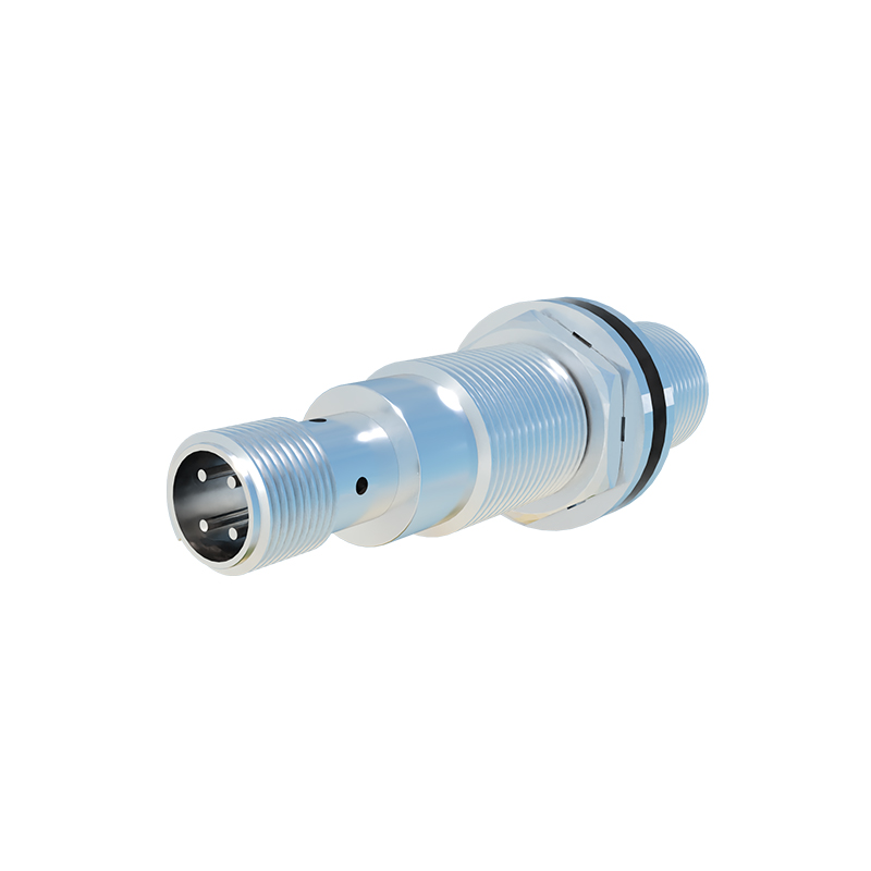
Photoelectric sensors use a light emitter (usually LED or laser) and a receiver. The measurement circuit here is focused on the receiver side, processing a weak photocurrent from a photodiode or phototransistor. In a modulated (pulsed) system, which is standard for immunity to ambient light, the circuit must synchronously detect the specific frequency of the emitted light. This involves amplifying the tiny AC signal from the receiver, often using a transimpedance amplifier to convert current to voltage, followed by band-pass filtering centered on the modulation frequency, and finally rectification and comparison to a threshold. Designing for high signal-to-noise ratio (SNR) is critical, especially in dusty or foggy conditions where light scattering occurs. The circuit must also handle a wide dynamic range, from a strong signal with a close, reflective target to a very weak signal at the maximum sensing distance.
Beyond the sensor-specific front-end, the output stage is a common critical element. Most industrial sensors provide a discrete digital output via an NPN or PNP transistor. The circuit driving this transistor must include protection against overcurrent (short-circuit), reverse polarity, and inductive load kickback from relays or solenoids, typically using clamping diodes and series resistors. For analog output sensors (e.g., 4-20mA or 0-10V), a precision voltage-to-current converter or a buffered amplifier stage is required, with emphasis on linearity, low drift, and compliance voltage.
Power supply design is equally crucial. Industrial voltage supplies (24V DC) are noisy. The measurement circuit requires local regulation and extensive filtering (using bulk, bypass, and ferrite beads) to create clean analog and digital supply rails for the sensitive oscillator and comparator stages. Implementing proper PCB layout techniques—such as separating analog and digital grounds, minimizing loop areas for high-frequency currents, and providing a solid ground plane—is not an afterthought but a necessity for stable operation.
In conclusion, an effective proximity sensor measurement circuit is a tailored system integrating physics, analog electronics, and noise mitigation strategies. It transcends simply making the sensor work; it ensures consistent, failsafe operation amidst the electrical noise, temperature swings, and physical contaminants of the factory floor. Successful implementation demands a deep understanding of the sensing principle, careful component selection, and rigorous attention to the details of circuit layout and protection.