In industrial automation and control systems, proximity switches, also known as proximity sensors, are indispensable components for non-contact detection of metallic or, in some cases, non-metallic objects. Their reliability hinges on precise sensing distance adjustment. Incorrect calibration can lead to missed detections, false triggers, or physical damage, compromising system integrity. This article provides a comprehensive, engineer-focused guide on the principles and practical steps for accurately adjusting the sensing distance of inductive and capacitive proximity sensors.
Understanding the Core Principle: The Sensing Field
The fundamental concept behind adjustment is manipulating the sensor's effective sensing field. This field is not a sharp line but a three-dimensional zone where the target object influences the sensor's internal oscillator or capacitance. The rated sensing distance (Sn), specified in datasheets, is the nominal operating point under standardized conditions (typically a standard target of mild steel). The real-world effective sensing distance (Sr) is influenced by the target's material, size, shape, and environmental factors. The goal of adjustment is to set a reliable operating point within Sr, often incorporating a safety factor, typically 70-80% of Sr, to account for variables like temperature drift, voltage fluctuations, and mechanical vibration.
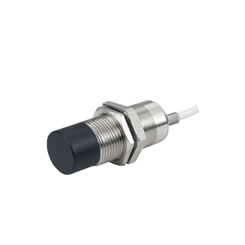
Step-by-Step Adjustment Procedure
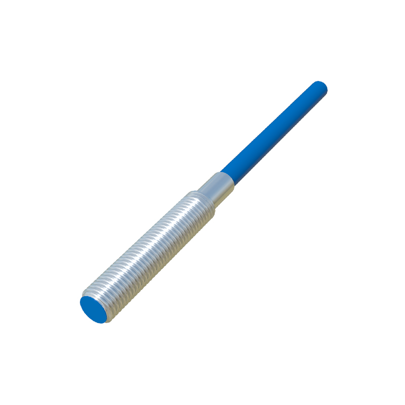
1. Initial Setup and Safety: Always de-energize the system before installation. Mount the sensor securely, ensuring it is aligned parallel to the expected path of the target object. For side-sensing models, maintain the recommended clearance from surrounding metal (as per datasheet) to prevent shielding effects. Re-apply power.
2. Target Selection: Use the actual target object or a representative test piece for adjustment. Remember, a stainless-steel target will have a reduced Sr compared to mild steel, while aluminum and brass have even greater reduction factors.
3. Locating the Adjustment Mechanism:
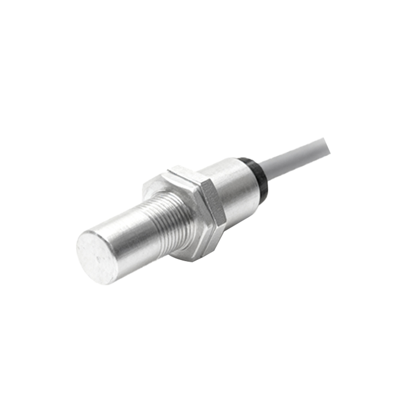
Potentiometer: The most common method. A small screwdriver-adjustable potentiometer, usually located on the back or side of the sensor housing. Clockwise rotation typically increases sensitivity (increases sensing distance), while counter-clockwise rotation decreases it.
Teach-In Function: Found on many modern programmable sensors. This involves presenting the target at the desired detection point and activating the teach-in mode via a separate wire, a button, or a magnetic tool. The sensor automatically calibrates its threshold.
DIP Switches: Some sensors offer discrete range settings (e.g., near/far) via internal DIP switches.
4. The Adjustment Process:
a. Start with the potentiometer at its minimum sensitivity (fully counter-clockwise).
b. Gradually bring the target object toward the sensor's active face.
c. The sensor's output will switch state (e.g., from OFF to ON for normally-open type) and its indicator LED will illuminate when the target enters the effective field.
d. Note this position. Slowly retract the target until the output switches back. Note this release point. The difference is the hysteresis zone, which prevents chatter.
e. Place the target at the precise operational distance required in your application.
f. Slowly increase the sensitivity (turn potentiometer clockwise) until the sensor's output just activates. Then, turn the potentiometer slightly further (e.g., an additional 5-10%) to establish the safety margin. Avoid over-adjusting to maximum sensitivity, as this makes the sensor prone to interference from adjacent metal, electrical noise, or environmental contaminants.
5. Verification and Stress Testing: After adjustment, perform multiple cycles with the target at the operational distance to ensure consistent triggering. Test edge cases: introduce the target slightly earlier and later than the set point. Monitor for false triggers under normal machine operation. For critical applications, verify performance at the extremes of the operating voltage and temperature range.
Advanced Considerations for Robust Operation
Temperature Compensation: Sensing distance can drift with temperature. High-quality sensors have built-in compensation circuits. For extreme environments, select sensors with wide temperature ratings and re-check calibration after thermal stabilization.
Mutual Interference: Installing two identical sensors in close proximity can cause them to affect each other's fields. Maintain the minimum separation distance specified by the manufacturer (often 2-3 times the sensor diameter).
Target Material & Size: For non-standard materials, apply the correction factor (K) from the datasheet: Effective Distance Sr = Rated Distance Sn × K. The target should ideally be larger than or equal to the sensor's sensing face.
Output State Configuration: Ensure the sensor's output logic (NPN/PNP, NO/NC) is correctly selected for your PLC or controller input module before adjustment. An incorrectly wired sensor will not respond as expected