In the realm of industrial automation and control systems, the accurate measurement of rotational or linear speed is paramount for ensuring operational efficiency, safety, and process integrity. Among the diverse array of sensing technologies available, proximity speed sensors stand out for their non-contact operation, robustness, and high reliability. These devices are engineered to detect the presence, absence, or passage of a target object and translate this information into a precise speed measurement, typically in revolutions per minute (RPM) or meters per second.
The fundamental operating principle of most industrial proximity speed sensors is based on electromagnetic induction or eddy current generation. A common type is the inductive proximity sensor used for speed sensing. It consists of a coil wound around a ferrite core, an oscillator, a detection circuit, and an output circuit. When a metallic target, such as a gear tooth, key, or specially mounted tab, passes within the sensor's sensing range, it disturbs the electromagnetic field generated by the oscillator. This disturbance causes a change in the oscillation amplitude or frequency, which is detected and converted into a clean, digital pulse signal by the internal circuitry. The frequency of this pulse train is directly proportional to the speed of the target. By counting the number of pulses over a known time interval, the rotational or linear speed can be accurately calculated. Other technologies, such as Hall-effect sensors, are also widely used. These sensors detect changes in magnetic field strength caused by a rotating magnet or a ferrous target passing by, generating a similar digital output pulse.
The advantages of using proximity sensors for speed measurement are significant. Their non-contact nature eliminates mechanical wear, ensuring a long operational lifespan and minimal maintenance. They are inherently resistant to contamination from oil, dust, and moisture, especially when housed in rugged, sealed enclosures typically rated IP67 or higher. This makes them ideal for harsh industrial environments found in manufacturing plants, mining operations, and heavy machinery. Furthermore, they offer high-resolution detection, capable of measuring very high speeds with excellent repeatability and fast response times. The output signal is usually a clean square wave compatible with programmable logic controllers (PLCs), frequency counters, tachometers, and other industrial control devices.
Applications for proximity speed sensors are vast and critical across numerous sectors. In automotive manufacturing and testing, they monitor the RPM of engines, wheel speeds for anti-lock braking systems (ABS), and conveyor line speeds. Within the power generation industry, they are essential for monitoring turbine shaft speed to prevent dangerous overspeed conditions. On conveyor systems in packaging and material handling, they ensure consistent line speed for process synchronization and bottleneck detection. They are integral to paper and steel mills for controlling roll speeds, in wind turbines for monitoring rotor speed, and in aerospace for testing auxiliary power units. Essentially, any application requiring reliable, real-time speed feedback from rotating shafts, gears, sprockets, or moving parts is a candidate for these sensors.
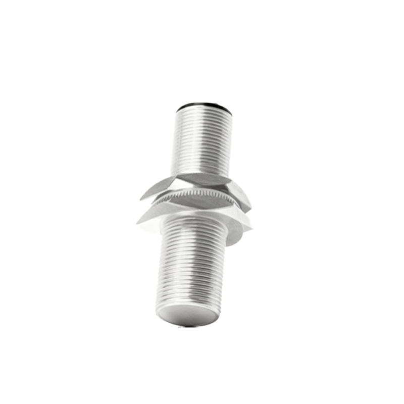
Selecting the appropriate proximity speed sensor requires careful consideration of several key parameters. First, the target material is crucial; standard inductive sensors require ferrous metals (steel, iron), while specialized versions can detect non-ferrous metals. Hall-effect sensors require a magnetic field source. The sensing distance must be specified to ensure the target passes within the effective range without risk of physical collision. Output type is another critical choice: NPN or PNP transistor outputs (sinking or sourcing) for direct PLC input, or push-pull configurations for flexibility. Some sensors offer analog outputs (4-20 mA or 0-10 V) proportional to speed. The operating frequency or maximum switching frequency defines the highest speed the sensor can reliably detect. Environmental factors such as ambient temperature, presence of strong electromagnetic interference (EMI), and required ingress protection (IP rating) must align with the installation conditions. Finally, mechanical considerations like housing style (threaded barrel, rectangular), size, and connection type (cable or connector) are important for physical integration.
Installation and setup are generally straightforward but demand attention to detail. The sensor must be mounted securely to prevent vibration-induced errors. The gap between the sensor face and the target must be adjusted to within the specified sensing range, often using a feeler gauge. For gear tooth detection, the sensor is typically aligned radially to the gear. Proper shielding and routing of cables are necessary to minimize electrical noise pickup. Regular maintenance, though minimal, involves periodic checks for physical damage, buildup of debris on the sensing face, and verification of signal integrity.
In conclusion, proximity speed sensors are indispensable components in modern industrial automation. Their ability to provide accurate, reliable, and non-contact speed feedback under demanding conditions makes them a cornerstone of machine monitoring, control, and protection systems. By understanding their operating principles, advantages, and key selection criteria, engineers and technicians can effectively deploy these sensors to enhance productivity,