Proximity sensors are ubiquitous in modern industrial automation, consumer electronics, and automotive systems. At the heart of many inductive proximity sensors lies a critical component: the sensing coil. Its design is not merely an electrical exercise but a multidisciplinary challenge involving electromagnetics, materials science, and practical manufacturing constraints. A well-designed coil dictates the sensor's sensitivity, range, response time, stability, and overall reliability.
The fundamental operating principle is based on electromagnetic induction. An alternating current in the coil generates a high-frequency oscillating magnetic field. When a conductive target enters this field, eddy currents are induced within the target. These eddy currents, in turn, generate their own opposing magnetic field, which interacts with the original field from the coil. This interaction alters the coil's effective impedance—its inductance and resistance. The sensor's electronics detect this change, typically as a shift in the frequency or amplitude of the oscillation, and trigger an output signal. The coil is the transducer that converts the physical presence of a target into a measurable electrical parameter.
Several key parameters govern coil design. First is the inductance value (L), which is primarily determined by the number of turns, coil diameter, and core material. A higher inductance can increase sensitivity but may reduce the maximum operational frequency. The quality factor (Q factor) is crucial; it represents the ratio of energy stored to energy dissipated per cycle. A high Q factor indicates a sharp resonant peak, leading to better sensitivity and signal-to-noise ratio. However, an excessively high Q can make the sensor prone to oscillation instability and more sensitive to environmental factors like temperature drift.
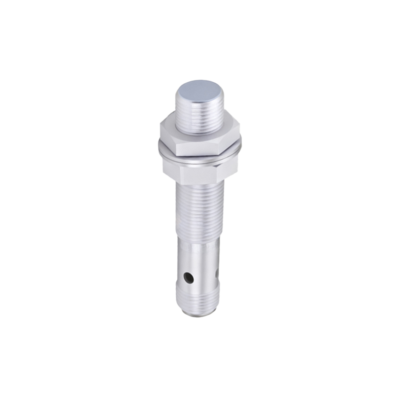
The choice of core material is pivotal. Air-core coils are simple but offer limited range and sensitivity. Ferrite cores, made from manganese-zinc or nickel-zinc compounds, concentrate the magnetic flux lines, significantly increasing inductance and effective sensing range for a given coil size. The shape of the core—such as cup-core, rod-core, or pot-core—directs the magnetic field, defining the sensor's sensing profile (axial or lateral). Pot cores, for instance, provide excellent shielding and a well-defined frontal sensing zone.
Wire selection involves trade-offs. Litz wire, composed of many individually insulated thin strands, is excellent for high-frequency applications as it mitigates the skin effect, reducing AC resistance and improving the Q factor. However, it is more expensive and harder to wind. Solid enameled copper wire is cost-effective and suitable for many standard applications. The winding geometry—whether layered, random, or precision-wound—affects parasitic capacitance and the consistency of the magnetic field.
Shielding is a critical design aspect. An unshielded coil has a larger, more diffuse magnetic field, which can lead to side-sensing and false triggers from adjacent metal objects. A shielded coil incorporates a ferrite cup or a metallic ring (often copper or aluminum) around the sides and rear. This confines the magnetic field to the front of the sensor, creating a more directional and precise sensing face, which is essential for dense installations.
Optimization is an iterative process balancing conflicting requirements. To increase sensing distance, designers might increase turns, use a high-permeability ferrite core, or raise the operating frequency. However, more turns increase resistance and parasitic capacitance, potentially lowering the Q factor and the maximum usable frequency. A higher frequency allows for a smaller coil but increases losses in the core and may exacerbate electromagnetic interference (EMI) issues.
Finite Element Method (FEM) magnetic simulation software has become an indispensable tool. It allows designers to model the coil, core, shield, and target in a virtual environment. Engineers can visualize magnetic flux density, calculate inductance changes with target proximity, and optimize geometry before prototyping. This reduces development time and cost significantly.
Environmental robustness must be designed in from the start. The coil assembly must withstand mechanical vibration, thermal cycling, and humidity. Potting compounds are often used to secure the windings and protect against moisture and contaminants. Temperature compensation circuits are frequently necessary because the resistivity of copper wire increases with temperature, changing the coil's DC resistance and affecting performance.
Finally, the design must align with manufacturability. Automated winding machines have limitations on wire gauge, turn count, and core shapes. The design should facilitate consistent, high-yield production. Tolerances on inductance and Q factor must be set with the production process's capability in mind.
In conclusion, proximity sensor coil design is a nuanced engineering task. There is no single optimal design; the ideal coil is the one that best meets the specific application's requirements for range, size, cost, response speed, and environmental endurance. By deeply understanding the electromagnetic principles and carefully weighing the trade-offs between core materials, winding techniques, shielding, and electronic drive circuitry, engineers can develop robust and high-performance proximity sensing