Proximity sensors are indispensable components in modern industrial automation, offering non-contact detection of objects within a defined range. Their reliability and versatility stem not only from the sensors themselves but also from the circuits that process their signals. Understanding common proximity sensor circuits is crucial for engineers designing, implementing, or troubleshooting automated systems. This article explores fundamental circuit configurations, their operational principles, and typical applications.
The core function of any proximity sensor circuit is to convert the physical phenomenon of detection—be it through inductive, capacitive, or photoelectric means—into a clean, usable electrical signal, typically a digital ON/OFF output. The most basic and widespread circuit is the Two-Wire DC Circuit. In this configuration, the sensor is connected in series with the load (e.g., a PLC input module). The sensor draws a small quiescent current (leakage current) when no target is present. Upon detection, it increases its internal impedance, allowing the majority of the supply voltage to appear across the load, signaling an ON state. Its primary advantage is simple wiring, similar to a mechanical switch. However, designers must carefully consider the leakage current to ensure it does not falsely trigger the load and the voltage drop to guarantee sufficient operating voltage for the sensor itself.
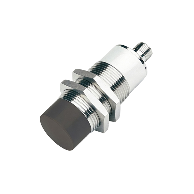
For applications requiring higher precision and lower leakage current, the Three-Wire DC Circuit is the standard. It features separate wires for power supply positive, power supply negative (common), and the output signal. This design isolates the sensor's power circuit from its switching circuit. Internally, it uses a solid-state switch (like an NPN or PNP transistor) to connect the output line either to the common negative (NPN sinking) or to the positive supply (PNP sourcing). This provides a crisp, full-voltage swing output with negligible leakage, making it highly compatible with programmable logic controllers (PLCs) and other control systems. The choice between NPN and PNP is often dictated by the prevailing convention of the control system's input card design.
While DC circuits dominate, AC Two-Wire Circuits are prevalent in environments where only AC power is available or for directly controlling AC loads like solenoids or contactor coils. These sensors contain a solid-state AC switch, such as a TRIAC. A key consideration here is the inrush current of the load and the minimal holding current required to keep the TRIAC conducting after switch-on. An undersized load may not draw enough holding current, causing the sensor to chatter or turn off unexpectedly. A bleed resistor or capacitor is often used in parallel with the load to mitigate this issue.
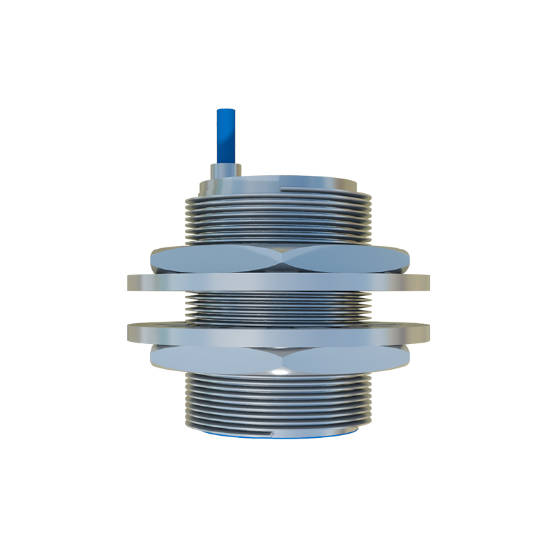
Beyond basic switching, Analog Output Circuits provide a continuous signal proportional to the distance to the target. Commonly offering 0-10V or 4-20mA outputs, these circuits integrate the sensing element with sophisticated signal conditioning. The analog value changes as the target moves within the sensor's sensing range, enabling applications like position monitoring, edge guidance, or thickness measurement. The 4-20mA standard is particularly valued for its noise immunity in electrically noisy industrial environments and its ability to indicate a wire break (0mA).
For specialized tasks, Circuits with Special Functions are employed. Namur sensors are intrinsically safe two-wire sensors designed for hazardous areas. They output a small current signal (e.g.,<1mA for OFF, >2mA for ON) to a separate barrier or isolator, which then provides the switching signal to the control system. IO-Link circuits represent the digital evolution, embedding a micro-controller that allows the sensor to transmit not just a switch state but also detailed parameter data (e.g., operating hours, temperature, detailed diagnostics) and receive configuration commands over the same three wires used for standard DC sensors.
When designing or applying these circuits, several critical factors must be addressed. Shielding and Cable Routing are paramount, especially for analog or high-frequency sensors. Cables should be kept away from power lines and motor drives to prevent electromagnetic interference. Short-Circuit and Overload Protection is often built into modern sensors but may require external fuses in harsh conditions. For DC circuits, ensuring correct Polarity is essential to prevent damage. Finally, Load Compatibility must be verified, checking that the sensor's output characteristics (voltage, current, switching type) match the requirements of the connected input device.
In conclusion, the effective deployment of proximity sensors hinges on selecting the appropriate circuit topology. From the simplicity of two-wire designs to the intelligence of IO-Link, each circuit serves a distinct purpose in the industrial ecosystem. A deep understanding of their operation, limitations, and best practices ensures robust, reliable, and maintainable automation solutions, forming the backbone of efficient manufacturing and process control systems.