In industrial automation and control systems, proximity sensors are indispensable components for detecting the presence or absence of objects without physical contact. A common configuration, especially in safety circuits or multi-point monitoring applications, is wiring these sensors in series. This article provides a detailed, professional guide on how to correctly wire inductive or capacitive proximity sensors in a series connection, adhering to standard electrical practices and safety protocols.
Understanding the Series Connection Concept
Wiring sensors in series means connecting the output signal wires of multiple sensors in a daisy-chain fashion, forming a single continuous path for the electrical current. In this configuration, the operational state of the entire circuit is dependent on all sensors. Typically, for a Normally Open (NO) output type wired in series, all sensors must detect a target (close their switch) to complete the circuit and allow current to flow to the load (e.g., a PLC input, relay coil, or indicator lamp). If any one sensor does not detect a target (its switch remains open), the circuit is broken, and the signal is lost. This is often referred to as an "AND" logic function: Sensor 1 AND Sensor 2 AND Sensor N must be activated for an output.
This method is fundamentally different from parallel wiring. Series connections are primarily used for creating interlock conditions, safety curtains, or multi-point verification systems where a specific sequence or condition involving all monitored points must be met.

Step-by-Step Wiring Procedure
Before starting any electrical work, ensure the power supply is locked out and tagged out (LOTO). Verify the sensor specifications (operating voltage, output type—PNP/NPN, NO/NC, current rating) are compatible with your power supply and load.
1. Circuit Design and Component Selection:
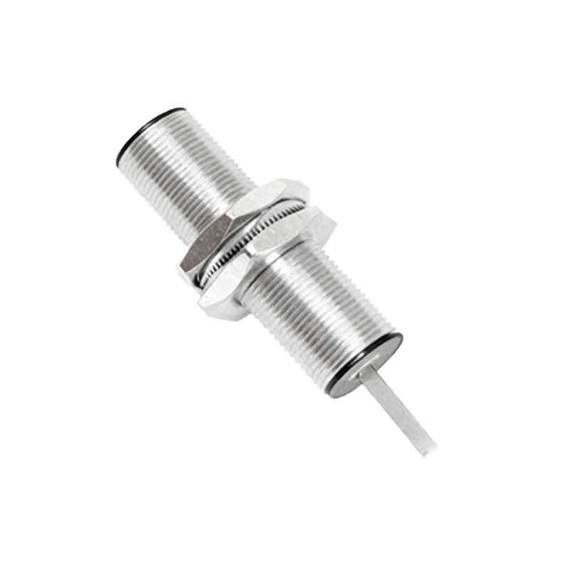
Determine the required logic. For a "all sensors on" signal, use Normally Open (NO) outputs in series. For a "any sensor off" signal (e.g., a fault monitor), you might use Normally Closed (NC) outputs, though this is less common and requires careful design to avoid confusion.
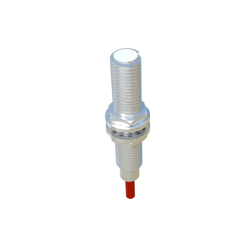
Calculate the total voltage drop. Each sensor's switch and internal circuitry has a small voltage drop. When wired in series, these drops add up. Ensure the voltage remaining at the load after all drops is within its operational range. Exceeding the maximum current rating of any single sensor in the chain must also be avoided.
Select a power supply with appropriate voltage and current capacity. A 24V DC supply is standard in industrial settings.
2. Wiring the Power Supply:
Connect the positive terminal of your DC power supply (e.g., +24V) to the brown wire (typically) or the V+ terminal of the first proximity sensor in the series chain.
Connect the negative terminal of your DC power supply (0V or common) to one terminal of your load (e.g., the PLC input common or one side of a relay coil).
3. Creating the Series Chain:
For sensors with a 3-wire configuration (Brown: +V, Blue: 0V, Black: Output):
Connect the Black (output) wire of Sensor 1 to the Brown (+V) wire of Sensor 2. This is the critical series link.
Connect the Black (output) wire of Sensor 2 to the Brown (+V) wire of Sensor 3. Continue this pattern for all subsequent sensors.
Connect the Black (output) wire of the last sensor in the chain to the remaining terminal of your load.
Commoning the Negative Lines: All Blue wires (0V) from every sensor must be connected together and then to the power supply's negative terminal (common). This provides the return path for the sensor's internal electronics. Do not wire the blue wires in series.
4. Connecting the Load:
The final connection runs from the output wire of the last sensor to the "hot" side of your load (PLC input, relay coil).
The other side of the load is already connected to the power supply common (0V), completing the circuit.
5. Testing and Diagnostics:
Apply power cautiously.
Activate each sensor individually with a target. The load should only energize when all sensors in the series are simultaneously activated.
Use a multimeter to check for voltage at key points: at the load when sensors are off/on, and across each sensor's switching element to verify proper operation.
An open circuit (broken wire, failed sensor, or inactive sensor) anywhere in the series will result in no signal at the load.
Important Considerations