Proximity sensors are essential components in modern industrial automation, offering non-contact detection of objects within their sensing range. This comprehensive guide provides an illustrated overview of various proximity sensor models, their working principles, and typical applications.
Inductive proximity sensors are widely used for detecting metallic objects. Common models include cylindrical types (e.g., M8, M12, M18, M30) and rectangular types. The M12 model, for instance, features a compact design with sensing distances ranging from 2mm to 4mm, ideal for tight spaces in machinery. These sensors operate on electromagnetic fields, generating eddy currents in metallic targets. Diagrams typically show internal components like oscillator coils, signal processors, and output circuits. Key specifications include sensing distance, response frequency, and output type (PNP/NPN).
Capacitive proximity sensors detect both metallic and non-metallic materials. Models such as the CR18-8DN and CR30-15DN offer adjustable sensitivity via potentiometers. Their diagrams illustrate electrode plates and oscillation circuits that measure capacitance changes. Typical sensing distances range from 3mm to 25mm, with applications in liquid level detection or plastic material handling.
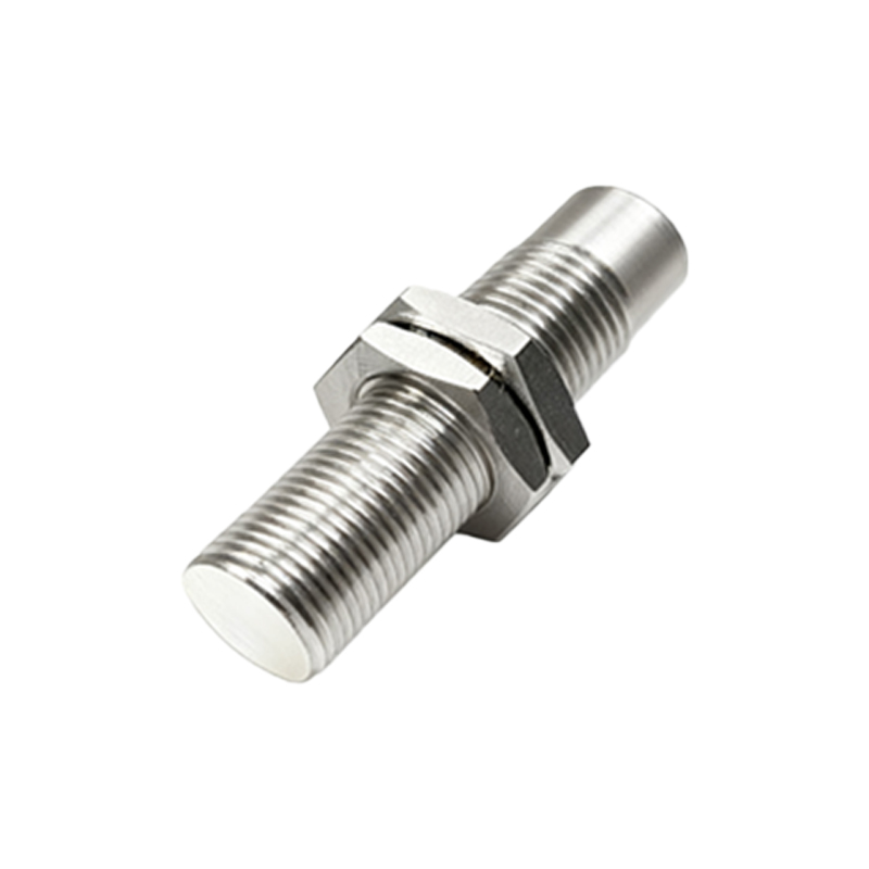
Ultrasonic proximity sensors, like the UC2000 series, use sound waves for long-range detection up to 2 meters. Diagrams depict transmitter/receiver modules and time-of-flight calculation circuits. These models excel in harsh environments where dust or moisture exists.
Magnetic proximity sensors (reed switch or Hall effect types) are compact models like the MH-20 series. Diagrams show magnetic field interaction with internal switches. They’re commonly used in position sensing for cylinders or safety door monitoring.
Photoelectric sensors, though sometimes categorized separately, include diffuse-reflective (e.g., E3Z-D61) and through-beam models. Their diagrams highlight LED/phototransistor arrangements and modulation circuits for immunity to ambient light.
When selecting models, consider factors like sensing distance (rated vs. actual), output configurations (2-wire/3-wire DC, AC models), and housing materials (brass, stainless steel, or PBT plastic). Industry standards like IEC 60947-5-2 define performance metrics. Installation diagrams demonstrate proper mounting clearances to avoid mutual interference between multiple sensors.
Advanced models now integrate IO-Link communication (e.g., Siemens SIMATIC series) for parameterization and diagnostics. Explosion-proof models (ATEX/IECEx certified) feature encapsulated designs shown in cross-sectional diagrams.
Maintenance tips include regular cleaning of sensing faces and verifying electrical connections via ladder diagrams in control systems. Troubleshooting charts often accompany technical documents to identify issues like unstable detection or short circuits.
In summary, proximity sensor selection depends on target material, environmental conditions, and required precision. Always refer to manufacturer datasheets for model-specific diagrams and specifications to ensure optimal system integration.