Inductive proximity sensors are fundamental components in industrial automation, widely used for non-contact detection of metallic objects. In electrical schematics, these sensors are represented by standardized symbols that convey critical information about their function, configuration, and electrical connections. Understanding these symbols is essential for engineers, technicians, and designers to accurately interpret circuit diagrams, ensure proper integration, and troubleshoot systems effectively.
The core symbol for an inductive proximity sensor typically consists of a coil representation enclosed within a geometric shape, often a circle or square, indicating the sensing element. This coil symbolizes the oscillator circuit that generates an electromagnetic field. When a metallic object enters this field, eddy currents are induced, causing a change in the oscillator's amplitude. This change is detected and converted into a switching signal. The housing shape around the coil may vary slightly between standards but generally denotes the sensor's body.
A crucial aspect of the symbol is the designation of the sensor's output type. This is indicated by graphical markers within or adjacent to the main symbol. The most common output types are:

1. PNP (Sourcing) Output: Represented by an arrow pointing outward from the symbol, signifying that the sensor switches the positive voltage line to the load.
2. NPN (Sinking) Output: Represented by an arrow pointing inward toward the symbol, indicating that the sensor switches the negative voltage line (ground) to the load.
3. Analog Output: Often shown with a wave symbol or the letters "AOUT," representing a continuous voltage or current signal proportional to the sensing distance.
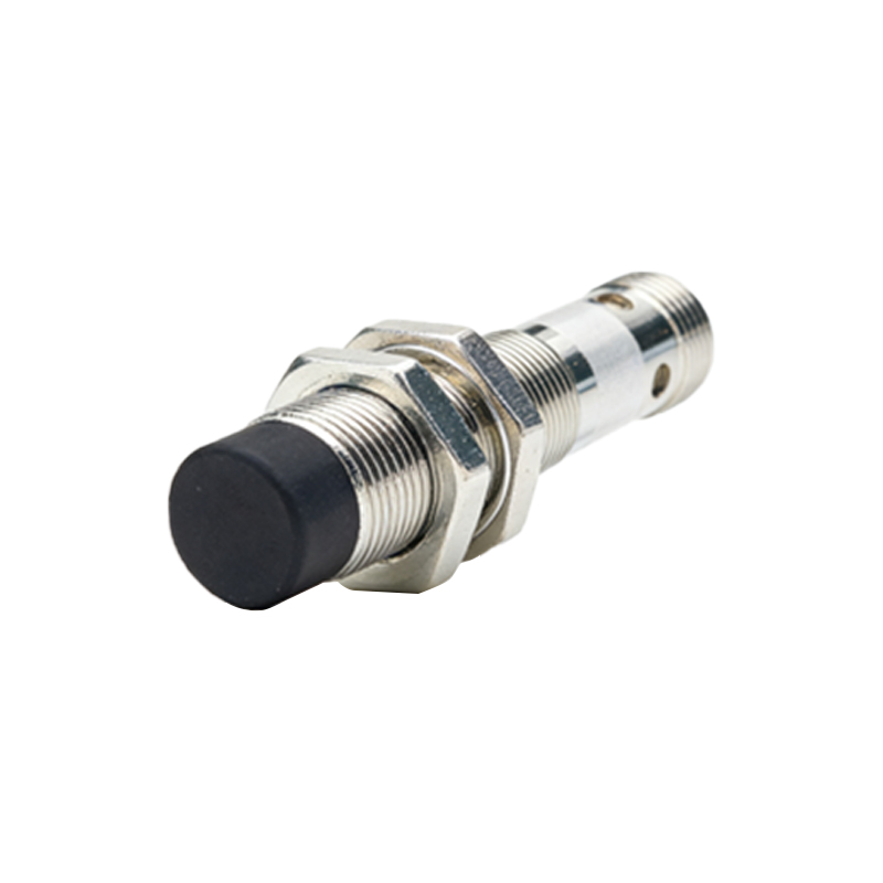
4. Namur Output: A specialized intrinsically safe output, usually denoted by the letter "N" or a specific code, used in hazardous areas.
The number of wires and their functions are also embedded in the schematic symbol. A standard three-wire DC sensor symbol will show connections for supply positive (typically +V or L+), supply negative (0V or L-), and the switched signal output. Two-wire AC/DC sensor symbols simplify this, showing only two connection points that carry both the supply power and the load current. The wiring diagram is sometimes integrated into the symbol or provided in a separate legend.
International standards play a significant role in symbol standardization. The International Electrotechnical Commission (IEC) standards (e.g., IEC 60617) and various national standards (like ANSI/IEEE in North America) provide guidelines. While the core concept is similar, minor stylistic differences in the enclosure shape, arrow styles, or internal markings may exist. A competent engineer must be familiar with the standard used in a particular drawing set.
Furthermore, symbols often include alphanumeric codes that specify key parameters. These may be placed next to the symbol or in a component list. Common codes include:
- Type Code: e.g., "IN" for inductive.
- Function Code: e.g., "B" for switch with memory function.
- Output State: Normally Open (NO) or Normally Closed (NC) contact indication, usually shown by the configuration of the switch symbol inside. A break in the line represents NO, while a connected line represents NC in the non-activated state.
In complex control system diagrams, such as those created in CAD software like EPLAN or AutoCAD Electrical, these symbols are stored in intelligent libraries. These libraries link the graphical symbol to a database containing technical data—sensing range, housing material, electrical ratings, and part numbers—ensuring consistency and accuracy across large projects.
Misinterpreting a sensor symbol can lead to wiring errors, incorrect PLC input module selection (sourcing vs. sinking), or improper safety circuit design. For instance, connecting a PNP sensor to an NPN-input PLC module will result in failure. Therefore, a meticulous review of the schematic symbols, alongside the sensor's datasheet, is a non-negotiable step in system design and installation.
As technology advances, symbols for newer variants, such as IO-Link inductive sensors that combine digital switching with analog and diagnostic data communication, are evolving. These may incorporate a small "IO-Link" notation or a special communication bus symbol adjacent to the traditional switching symbol, indicating their smart capabilities.
In summary, the symbol of an inductive proximity sensor on an electrical schematic is a dense packet of information. It encodes the physical principle, electrical output type, wiring configuration, and functional logic. Mastery of these symbols is not merely an academic exercise but a practical necessity for designing, installing, and maintaining robust, efficient, and safe automated systems. Always cross-reference the schematic symbol with the manufacturer's documentation for absolute clarity.