Proximity sensors, the silent sentinels of modern automation, are marvels of precision engineering. Their manufacturing process is a meticulous symphony of material science, electronics assembly, and rigorous quality control. This guide delves into the core production stages, adhering to industry standards and best practices.
The journey begins with the Component Sourcing and Inspection. High-grade raw materials are non-negotiable. This includes the sensing element (often a ferrite core for inductive types or an IR LED/phototransistor for optical types), copper wire for coils, semiconductor chips for oscillation and signal processing, durable housing materials like PBT or nickel-plated brass, and epoxy resins for potting. Incoming materials undergo stringent tests—dimensional checks, electrical property verification, and material composition analysis—to ensure batch consistency and long-term reliability.
Next is the Core Sub-Assembly Phase. For inductive proximity sensors, this involves winding the coil. Automated winding machines precisely layer hundreds of turns of ultra-fine enameled copper wire around the ferrite core. The consistency of winding tension and layering is critical, as it directly influences the sensor's sensitivity and switching frequency. Simultaneously, the oscillator and amplifier circuit is populated onto a printed circuit board (PCB) using Surface Mount Technology (SMT). High-speed pick-and-place machines accurately position micro-components, which are then soldered in a reflow oven, creating a robust electrical foundation.
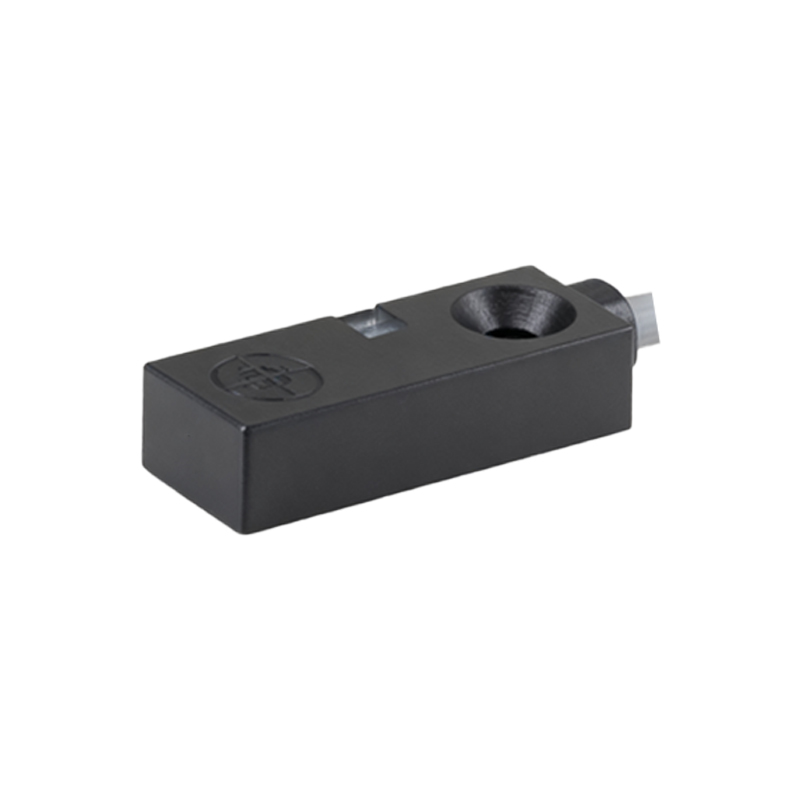
The Assembly and Integration stage is where the sensor takes physical form. The wound coil is carefully connected to the PCB. The assembled electronics are then precisely fitted into the sensor housing. For shielded (flush-mountable) variants, the ferrite core and coil are positioned at the front, enclosed by a metallic sensing face that directs the electromagnetic field. For unshielded types, the coil extends to the housing edge for a longer sensing range. Meticulous attention is paid to alignment, as any deviation can cause significant performance asymmetry.
Following assembly, the unit enters the most critical phase: Potting and Sealing. The internal cavity is filled with a thermosetting epoxy resin compound. This process serves multiple vital functions: it immobilizes all internal components against vibration and shock, provides exceptional thermal conductivity to dissipate heat, and creates a hermetic seal against contaminants like dust, oils, and coolants. The potting compound is degassed to eliminate air bubbles, cured in controlled ovens, and inspected to ensure complete, void-free encapsulation. This step is paramount for achieving high Ingress Protection (IP) ratings like IP67 or IP69K.
No sensor leaves the factory without passing through the Calibration and Functional Testing corridor. Here, each unit is subjected to a battery of automated tests. Key parameters are calibrated and verified:
Switching Point Accuracy: The sensor is tested against certified reference targets at its nominal sensing distance. Hysteresis (the difference between the switch-on and switch-off points) is measured.
Frequency Response: For AC-powered or fast-responding models, the maximum switching frequency is tested.
Temperature Drift: Sensors are cycled through temperature chambers to ensure performance stability across their specified operating range (e.g., -25°C to 70°C).
Electrical Characteristics: Output current, leakage current, voltage drop, and short-circuit protection are all validated.
Environmental Robustness: Samples from each batch undergo stress tests, including vibration, shock, and endurance cycling, to validate design life.
Finally, Laser Marking and Final Packaging occurs. Critical data—part number, sensing distance, supply voltage, output type (PNP/NPN, NO/NC), and certification marks (CE, UL)—are permanently laser-etched onto the housing. Sensors are then packaged in anti-static materials, often with mounting accessories, and prepared for shipment.
The entire process is governed by a Quality Management System (QMS) like ISO 9001, with traceability at its heart. From raw material lot numbers to final test results, every data point is recorded, ensuring that any field issue can be investigated back to its root cause in the production line.
In conclusion, manufacturing a high-quality proximity sensor is far more than simple assembly. It is an integrated process demanding precision engineering, controlled material science, and uncompromising testing. Each step, from coil winding to hermetic potting, is designed to deliver the reliability, accuracy, and durability that industrial automation systems depend on for seamless, uninterrupted operation.