In the rapidly evolving landscape of industrial automation and precision measurement, laser sensors have become indispensable tools. Their ability to provide non-contact, high-accuracy, and high-speed detection makes them vital across numerous sectors, including manufacturing, robotics, automotive, and aerospace. This guide offers a comprehensive overview of laser sensor technology, supported by detailed application diagrams, to assist engineers and technical professionals in selection and implementation.
Fundamentally, a laser sensor operates by emitting a focused beam of light toward a target. The sensor then analyzes the reflected light to determine specific parameters such as distance, displacement, position, or presence. The core technologies can be broadly categorized into three types: triangulation, time-of-flight (ToF), and confocal measurement. Each principle suits different application requirements concerning range, resolution, and environmental conditions.
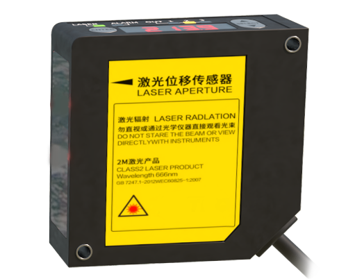
Triangulation-based laser sensors are renowned for their exceptional resolution at short to medium ranges. In this method, the laser emitter, the point of reflection on the target, and the receiving element (like a CCD or CMOS array) form a triangle. By calculating the angle of the reflected beam, the sensor determines the distance to the target with micron-level precision. Typical applications include precise thickness measurement of materials, surface contour profiling, and weld seam tracking. A detailed diagram would illustrate the emitter, the target surface, the receiver, and the angular relationship that enables precise calculation.
For longer-range applications requiring robust performance, Time-of-Flight (ToF) sensors are the preferred choice. These sensors measure the time it takes for a laser pulse to travel to the target and back. Given the constant speed of light, the distance is calculated directly. Modern ToF sensors can measure distances from a few centimeters up to several hundred meters. They are extensively used in warehouse automation for pallet dimensioning, in mobile robotics for navigation and obstacle avoidance, and in logistics for volume measurement. An accompanying diagram would typically show the emission of a laser pulse, its reflection, and the timing circuitry that computes the distance.
Confocal chromatic sensors represent the pinnacle of precision for measuring displacement, thickness, and surface topography on reflective, transparent, or multi-layered materials. They use white light, where different wavelengths focus at different distances. A spectrometer analyzes the reflected light's wavelength to determine the exact position of the target surface. This technology is crucial in semiconductor inspection, transparent glass thickness measurement, and biomedical device manufacturing. A schematic diagram for this technology is more complex, depicting the polychromatic light source, the chromatic lens system, and the spectral analyzer.
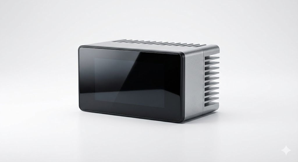
Beyond the measurement principle, selecting the right laser sensor involves a careful analysis of key specifications. Resolution, the smallest detectable change, is paramount for precision tasks. Repeatability defines the sensor's consistency in providing the same reading under unchanged conditions. The measuring range specifies the minimum and maximum distances over which the sensor operates accurately. Environmental factors like ambient light, dust, smoke, and target surface characteristics (color, reflectivity, material) significantly impact performance. Many modern sensors incorporate intelligent features like background suppression, teach-in functionality for easy setup, and robust housings with high IP ratings for durability in harsh industrial environments.
Integration into a control system is a critical step. Most laser sensors provide digital outputs (PNP/NPN, Push-Pull) or analog outputs (0-10V, 4-20mA) for seamless connection to PLCs (Programmable Logic Controllers) and data acquisition systems. Communication via industrial protocols like IO-Link is becoming increasingly common, enabling advanced parameter setting, condition monitoring, and diagnostic data retrieval. A system integration diagram is invaluable here, showing the sensor's power supply, output wiring to a PLC input module, and the subsequent data path to an HMI (Human-Machine Interface) or SCADA system.
To visualize these concepts, a master summary diagram is essential. This diagram would not depict a single sensor but rather a flowchart or decision matrix guiding the selection process. It begins with the application requirement: What needs to be measured (distance, profile, presence)? What are the environmental conditions? What accuracy and speed are needed? The chart then branches out to the primary technology types (Triangulation, ToF, Confocal). Under each branch, it lists typical specifications (range, resolution), ideal target surfaces, common industry applications, and a symbolic icon of the measurement principle. Finally, it points toward the necessary output type and integration method. Such a diagram serves as a powerful at-a-glance reference for engineers during the specification phase.
In conclusion, the effective deployment of laser sensors hinges on a deep understanding of the underlying technologies and a systematic approach to selection. By leveraging detailed application diagrams and comprehensive summary charts, engineering teams can demystify the specification process. This ensures the chosen sensor delivers optimal performance, enhances productivity, and contributes to the overall reliability and efficiency of automated systems. As technology advances, with trends like miniaturization, higher speeds, and embedded AI for data analysis, these visual guides will remain crucial tools for harnessing the full potential of laser sensing solutions.