Flat proximity sensors represent a significant advancement in industrial automation, offering unique advantages in space-constrained applications. Unlike traditional cylindrical sensors, their low-profile, rectangular design allows for seamless integration into machinery with limited mounting depth. This article provides a technical overview of flat proximity sensor images, explaining their operational principles, key visual features, and how to interpret their specifications from datasheet imagery.
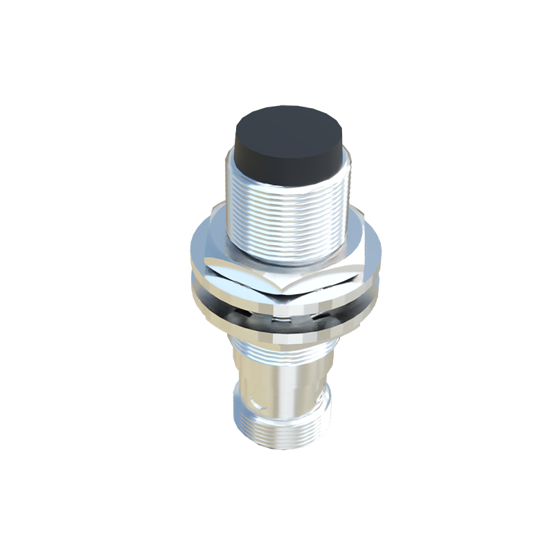
The primary visual characteristic of a flat proximity sensor is its housing. Images typically show a compact, often rectangular or square-shaped unit with a flat sensing face. This face is the active area where the electromagnetic field is emitted and received. The housing material, usually depicted in high-quality product photos, is made from durable plastics like PBT or metals such as stainless steel, indicating the sensor's ingress protection (IP) rating and suitability for harsh environments. Key markings visible in close-up images include the part number, sensing distance (e.g., 2mm, 5mm, 10mm), voltage range (e.g., 10-30V DC), and output type (PNP/NPN, NO/NC). The electrical connection is another critical visual element. Most flat sensors feature a fixed cable or a compact connector, such as a 4-pin M8 or M12 micro-style connector, which is clearly visible in installation diagrams. The color of the cable or connector body often follows industry standards, with brown representing the positive supply, blue for negative, and black for the output signal.
Interpreting internal diagrams is crucial for engineers. Cross-sectional views, often found in technical manuals, reveal the internal coil arrangement and the electronic components potted in resin. This illustrates the "flat" coil design that generates a parallel electromagnetic field, ideal for detecting objects approaching head-on. Comparison images are particularly valuable. Side-by-side visuals contrasting a flat sensor with a standard cylindrical sensor highlight the dramatic reduction in required mounting space. Application photos demonstrate real-world use, such as sensors mounted on the narrow side of a robotic gripper to detect workpiece presence or embedded within a conveyor frame for precise object counting without protruding.
When evaluating flat proximity sensor images for selection, engineers must scrutinize several details. The stated sensing distance (Sn) is calibrated for a standard target (usually mild steel). Images sometimes include graphs showing the reduction factor for different materials like aluminum, copper, or stainless steel. The presence of LED indicators, often a small red or green light visible in product photos, signifies a diagnostic feature for easy status monitoring. Mounting details are also visually communicated; many flat sensors have integrated M3 or M4 threaded holes or through-holes for bracket-free installation. Flush-mounting capability, a key advantage, is shown in cutaway drawings where the sensor can be embedded into a metal bracket without loss of sensing range, unlike cylindrical sensors which require a non-metallic surround.
In conclusion, flat proximity sensor images are not merely promotional tools but essential technical documents. From the external housing and connector type to internal cross-sections and application scenarios, each visual element provides critical data for ensuring correct sensor selection, installation, and integration. By carefully analyzing these images alongside datasheet specifications, automation engineers can leverage the space-saving and performance benefits of flat proximity sensors to optimize machine design and enhance system reliability.