Understanding how to wire a proximity switch correctly is crucial for ensuring reliable operation in industrial automation, machinery, and safety systems. A proximity switch, also known as a proximity sensor, detects the presence or absence of an object without physical contact, typically using inductive, capacitive, or magnetic principles. This guide provides a detailed explanation of common wiring configurations, based on real-world diagrams and practical applications.
Most proximity switches feature three primary terminals: brown (positive), blue (negative), and black (output). In a standard DC inductive proximity switch, the brown wire connects to the positive supply voltage (typically 10-30V DC), while the blue wire links to the common ground or negative terminal. The black wire serves as the output signal line, which switches state (open or closed) when an object enters the sensing range. For AC-powered models, wiring may involve live (brown) and neutral (blue) connections, with the output (black) managing load control.
A typical wiring diagram illustrates these connections in a straightforward loop. The power supply connects to the sensor’s brown and blue wires, establishing the circuit. The output black wire then routes to the load—such as a relay, programmable logic controller (PLC) input, or indicator light. In a normally open (NO) configuration, the output closes to complete the circuit when an object is detected; in a normally closed (NC) setup, the output opens upon detection. Diagrams often include protective elements like fuses or surge suppressors to guard against voltage spikes, especially in environments with inductive loads like solenoids or motors.
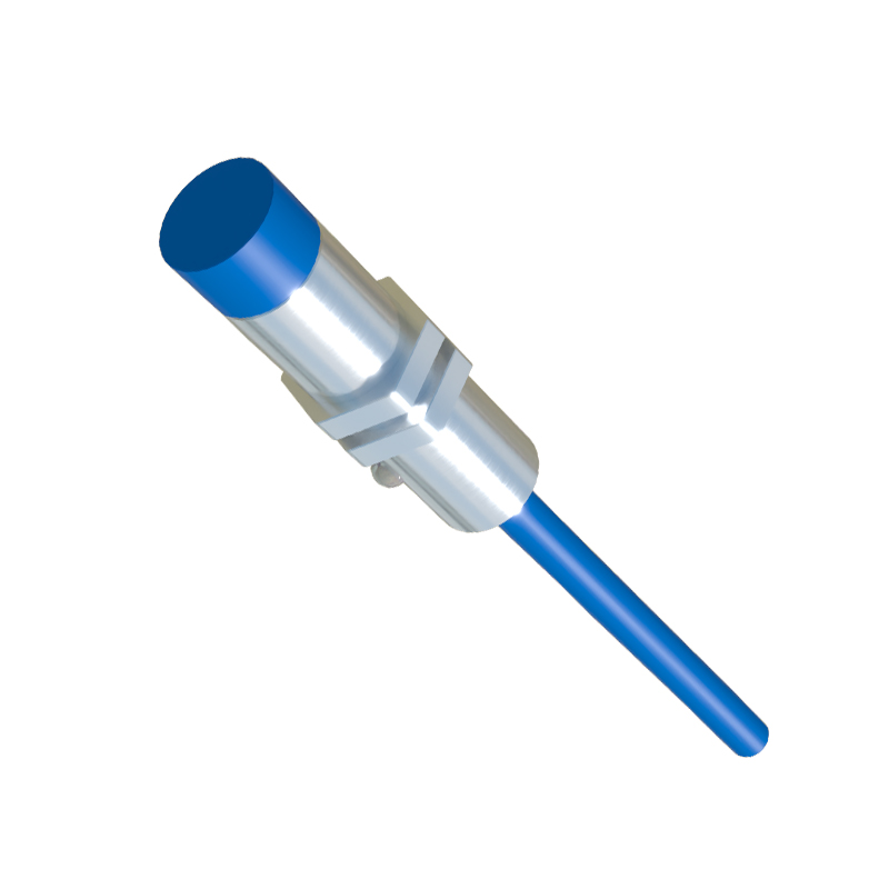
Wiring considerations extend beyond basic connections. Shielded cables are recommended for long runs or electrically noisy environments to prevent interference. Proper grounding of the sensor housing and cable shield minimizes false triggering. Additionally, ensuring correct polarity is vital—reversing brown and blue wires on DC sensors can damage the unit. For two-wire AC/DC proximity switches, wiring integrates both power and load in series, requiring careful calculation of voltage drop to avoid malfunction.
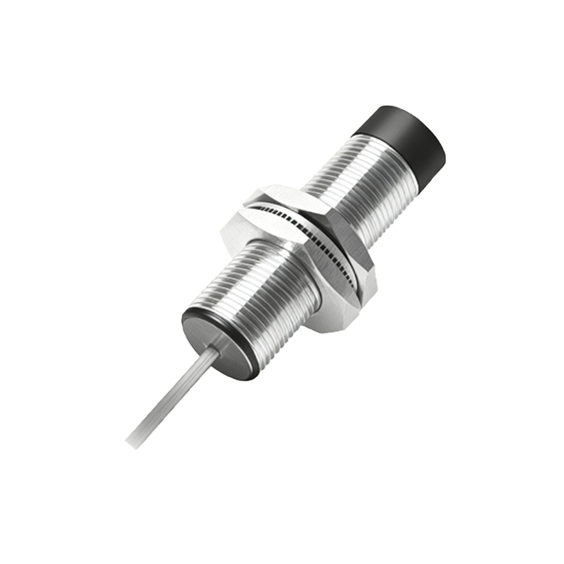
Real-world examples highlight practical nuances. In conveyor systems, inductive proximity switches often wire to PLC digital inputs to count packages or detect jams. Here, the black output wire connects to the PLC’s input terminal, with a common ground shared between the sensor and PLC power supply. Diagrams for such setups emphasize isolation to prevent ground loops. In hazardous areas, intrinsically safe circuits incorporate barriers, with diagrams showing specific connections to limit energy flow.
Troubleshooting wiring issues involves checking voltage at the sensor terminals, verifying output response with a multimeter, and inspecting for loose or corroded contacts. Common problems like no output signal often stem from incorrect power supply ratings, wiring faults, or misaligned sensing targets. Reference diagrams typically include diagnostic steps, such as measuring resistance between terminals or testing with a known good load.
In summary, proximity switch wiring diagrams serve as essential roadmaps for installation and maintenance. By following standardized color codes, adhering to manufacturer specifications, and integrating protective measures, users can ensure optimal performance and longevity. Whether for simple presence detection or complex automated processes, accurate wiring underpins the reliability of these versatile sensors.