Effective installation management of magnetic proximity sensors is critical for ensuring optimal performance, reliability, and longevity in industrial automation and control systems. As a seasoned electrical engineer, I have observed that many system failures can be traced back to oversights during the installation phase. This article outlines a comprehensive management framework for the successful deployment of these essential components.
The foundation of proper management lies in meticulous pre-installation planning. Before any physical work begins, engineers must conduct a thorough review of the sensor specifications, including sensing distance, switching frequency, output type (PNP/NPN, NO/NC), voltage ratings, and housing material (e.g., brass, stainless steel). Equally important is understanding the operational environment. Will the sensor be exposed to extreme temperatures, corrosive chemicals, heavy vibration, or strong electromagnetic interference? These factors dictate the selection of appropriately rated sensors, such as those with increased IP (Ingress Protection) ratings or welded stainless-steel housings for harsh conditions. Creating detailed installation drawings that specify mounting locations, orientation, and clearances from other machinery is non-negotiable. A common oversight is failing to account for the specific magnetic field characteristics of the target actuator (the moving part equipped with a trigger magnet). The effective sensing range can be significantly altered by the magnet's size, strength, and material.
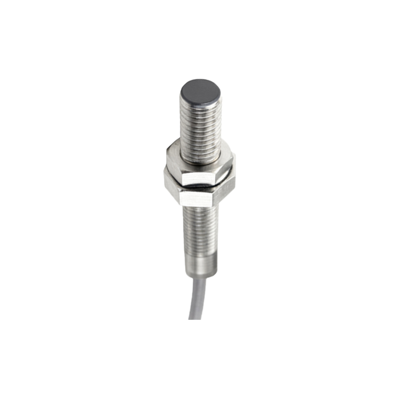
During the physical installation phase, adherence to manufacturer guidelines is paramount. Mounting stability is the first concern. Sensors must be securely fastened using the recommended hardware to prevent misalignment due to vibration, which is a primary cause of erratic operation. The alignment between the sensor face and the trigger magnet is critical; even a slight angular deviation can reduce the effective sensing distance. Use precision tools like dial indicators or laser alignment systems for critical applications. Maintain the specified gap between the sensor and the magnet during the actuator's travel. This gap is often much smaller than the maximum rated sensing distance to ensure a reliable signal margin. For cylinder-mounted sensors, ensure the mounting bracket does not flex and that the sensor can be micro-adjusted after installation.
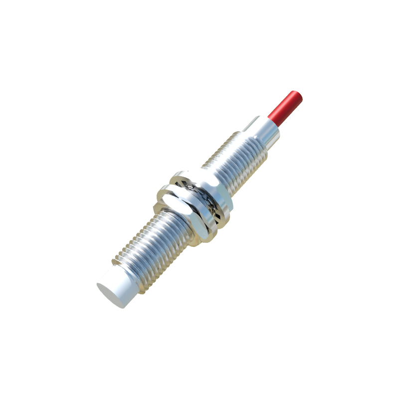
Wiring and electrical integration require disciplined management. Always follow local and national electrical codes (e.g., NEC, IEC). Use shielded cables in environments with high EMI and ground the shield properly at the control panel end only to prevent ground loops. Pay close attention to wire routing; keep signal lines away from power cables and motor leads to minimize noise induction. For DC sensors, correct polarity is essential to prevent immediate damage. Implement proper circuit protection, such as fuses or circuit breakers, and consider surge protection devices if the sensor is connected to long wire runs or inductive loads. Label all wires and connections clearly at both ends according to the schematic diagram—this simple practice saves invaluable time during troubleshooting and future maintenance.
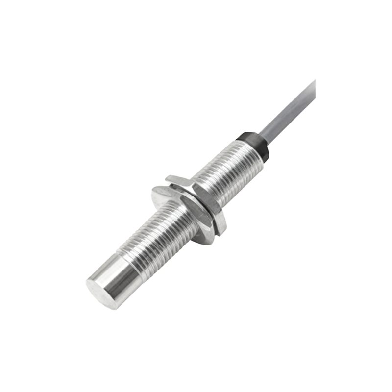
Post-installation commissioning and documentation form the final, crucial pillar of management. Do not assume the system works because the sensor is powered. Develop a systematic commissioning checklist: verify the sensor's LED indicator activates within the specified range, measure the actual switching point with the actuator in motion, and confirm the signal integrity at the PLC or controller input using a multimeter or the controller's diagnostic software. Test under all possible machine cycles and load conditions. Document every step. As-built drawings, sensor part numbers, installation photos, alignment settings, and test results should be compiled into a project dossier. This documentation is not bureaucratic; it is a vital asset for predictive maintenance and swift fault resolution.
Finally, establish a proactive maintenance schedule. While magnetic proximity sensors are largely maintenance-free, their performance should be periodically verified. Schedule inspections to check for physical damage, loose mounting hardware, corrosion, and accumulated metallic debris on the sensor face, which can attenuate the magnetic field. Monitor the system for increased error rates or signal dropouts, which may indicate a weakening trigger magnet or a slowly drifting alignment.
In conclusion, managing magnetic proximity sensor installation is a systematic engineering discipline that bridges the gap between component selection and long-term operational success. It demands a fusion of theoretical knowledge, practical skill, and rigorous procedural adherence. By investing in detailed planning, precise execution, thorough testing, and comprehensive documentation, electrical engineers can ensure these robust devices deliver their full potential in creating resilient and efficient automated systems.