Proximity switch sensors are fundamental components in modern automation, industrial control, and safety systems. Understanding their schematic diagram is crucial for engineers, technicians, and hobbyists involved in designing, troubleshooting, or implementing these devices. Unlike a simple mechanical switch, a proximity sensor detects the presence or absence of an object without physical contact, typically through electromagnetic fields, light, or sound. The schematic diagram provides a symbolic roadmap of the electronic circuitry that makes this non-contact detection possible.
At its core, the schematic for a standard inductive proximity sensor, one of the most common types, reveals several key sections. The heart of the circuit is the oscillator. This stage generates a high-frequency electromagnetic field at the sensing face of the device. In the schematic, this is represented by an inductor (the sensing coil), capacitors, and an oscillator IC or transistor network. The inductor symbol is central, as it physically creates the detection field. When a metallic target enters this field, eddy currents are induced in the target, which loads the oscillator circuit. This loading effect causes a change in the oscillator's amplitude or frequency.
This change is then fed into a trigger or threshold detection circuit. This stage, shown with comparator ICs or specific trigger components, monitors the oscillator's signal. When the change exceeds a predefined threshold—indicating a target is present—the trigger circuit activates. The schematic clearly shows the connection from the oscillator output to the input pin of the comparator.
The output of the trigger circuit drives the output stage. This is where the sensor interfaces with the larger control system, such as a PLC (Programmable Logic Controller). Schematics depict this section with a power transistor (like a MOSFET) or a solid-state relay symbol. For a 3-wire DC sensor, common configurations are NPN (sinking) or PNP (sourcing) outputs. The symbols for the transistor, its protection diode, and the connections for the supply voltage (V+), ground (GND), and output signal wire (OUT) are clearly labeled. Some advanced schematics also include a hysteresis circuit to prevent output chatter when a target is at the exact detection point.
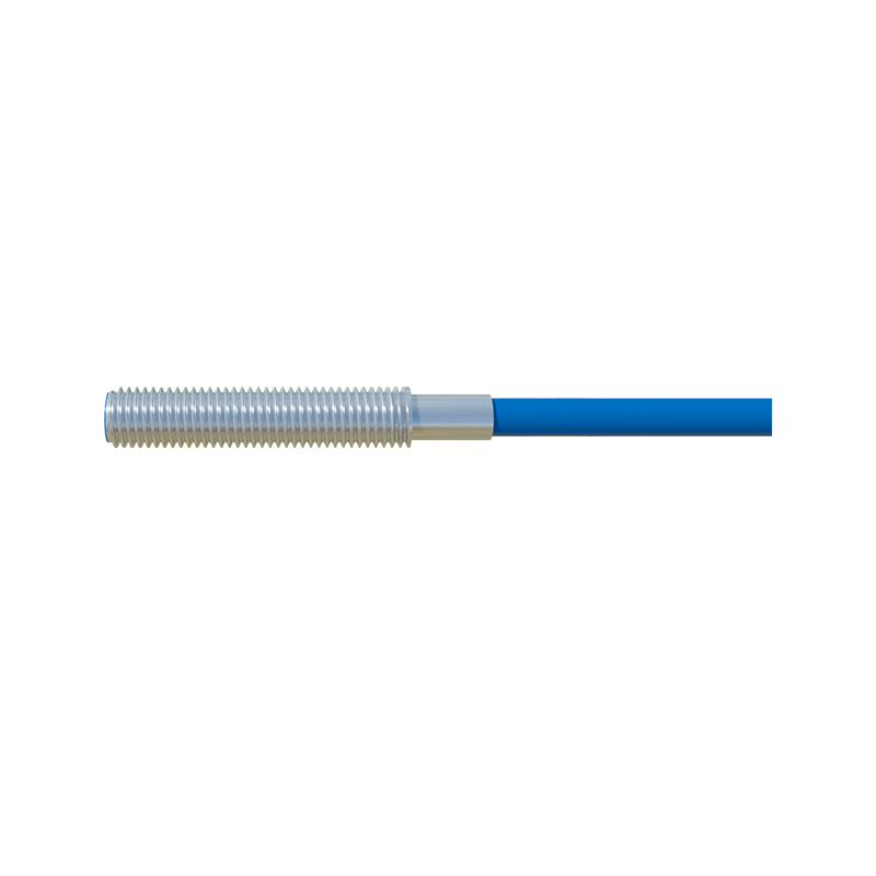
Capacitive proximity sensor schematics share a similar structure but are designed to detect both metallic and non-metallic materials. The key difference lies in the oscillator circuit, which is configured to be sensitive to changes in capacitance. The sensing electrode, represented by a special capacitor symbol, forms part of the oscillator's resonant circuit. The approach of any material alters the dielectric constant and thus the capacitance, which the circuit detects.
For photoelectric sensors, the schematic diverges significantly. It will show symbols for an infrared or visible light emitter (an LED or laser diode) and a phototransistor or photodiode receiver. The processing circuit is focused on amplifying the tiny receiver current and discriminating between the received light and ambient light interference. Ultrasonic sensor schematics feature symbols for a piezoelectric transducer for both emitting and receiving sound waves, coupled with timing circuits to measure the echo return time.
Reading a proximity sensor schematic requires understanding these standard symbols and stages: the power supply section (with reverse polarity and surge protection), the oscillator/sensing element, the trigger/comparator, and the output switch. It also reveals critical components for reliability: voltage regulators, filtering capacitors, and protection devices like TVS diodes against voltage spikes. By studying the schematic, one can diagnose common failures—such as a damaged output transistor, a faulty oscillator component, or issues with the power regulation—and understand the sensor's behavior under different electrical conditions. This knowledge is indispensable for effective system integration and maintenance.