In the realm of industrial automation and control systems, proximity sensors stand as fundamental components for non-contact object detection. This article delves into the practical aspects of these devices through an examination of real-world images and a detailed technical breakdown, catering to engineers and technicians seeking a deeper understanding of their physical construction and operational context.
A visual inspection of various proximity sensor models reveals distinct design philosophies tailored to specific applications. Inductive proximity sensors, commonly used for metal detection, typically feature a robust, cylindrical metallic housing with a sensing face made of a specialized polymer or ferrite material. This face is often color-coded, with a black or blue ring indicating its active area. The housing is threaded for easy mounting in standard industrial enclosures or directly onto machinery. Connection is facilitated via a pre-wired cable or a quick-disconnect plug system, with the cable gland providing crucial ingress protection (IP67/IP69K ratings are standard for harsh environments). The body is usually marked with critical information: the sensing distance (e.g., 5mm, 10mm), operating voltage (10-30V DC being most common), output type (PNP/NPN, NO/NC), and part number. In contrast, capacitive proximity sensors, designed to detect both metallic and non-metallic objects, often have a larger sensing face area and might feature a potentiometer for sensitivity adjustment, accessible under a protective rubber cap.
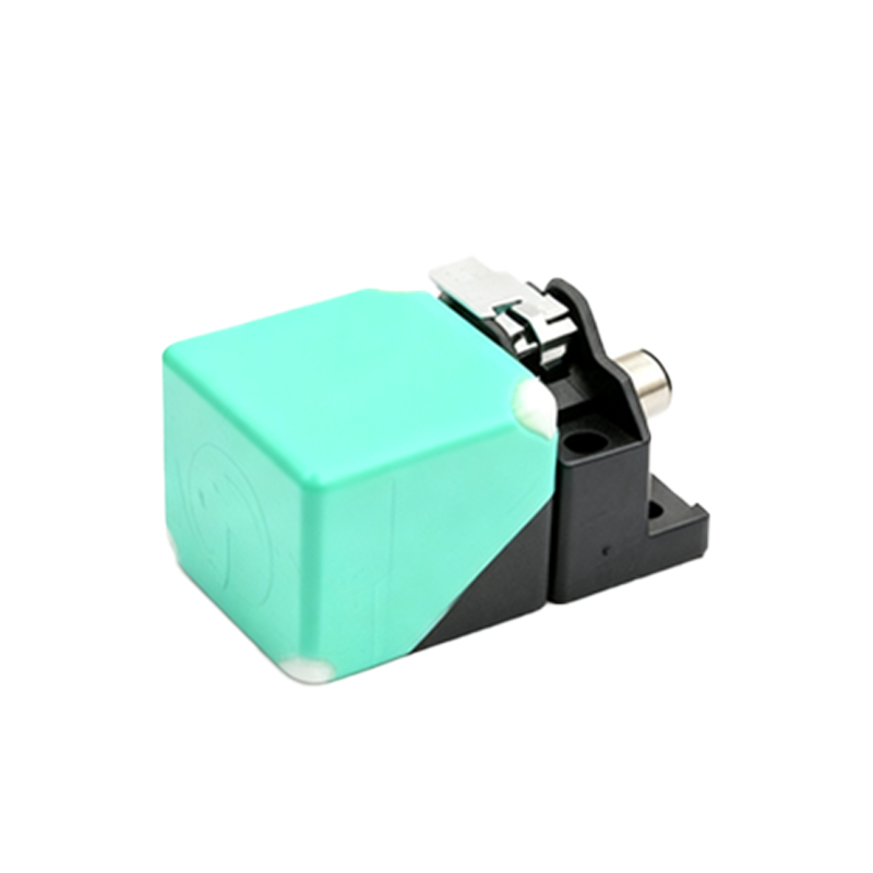
Photographs of ultrasonic and photoelectric proximity sensors show more complex geometries. Ultrasonic sensors possess distinct transmitter and receiver openings, often in a rectangular or cylindrical form factor. Photoelectric sensors, especially the diffuse-reflective type, have a lens assembly housing both the LED light source and the phototransistor receiver. Through-beam models are clearly two-part systems: a separate emitter and receiver unit. The build quality evident in these images underscores industrial durability, with materials like nickel-plated brass, stainless steel (V4A/AISI 316L for corrosive settings), and high-grade engineering plastics (PBT, PPS) resisting mechanical stress, cutting fluids, and washdown procedures.
Internally, the components visible in cutaway or exploded-view diagrams are key to function. The core of an inductive sensor is a coil wound around a ferrite core, connected to an oscillator circuit. When a metallic target enters the electromagnetic field, it induces eddy currents, causing a change in oscillation amplitude detected by a threshold circuit, which then switches the solid-state output. The capacitive sensor's front electrode forms one plate of a capacitor, with the target or background as the other; changes in capacitance are measured by an RC oscillator circuit. The sophistication of the integrated ASIC (Application-Specific Integrated Circuit) is noteworthy, providing temperature compensation, short-circuit protection, and immunity to electrical noise—a critical feature in electrically noisy plant environments.
Analyzing installation images highlights best practices. Correct mounting is paramount: ensuring the recommended lateral and axial clearance from metal surrounds to prevent false triggering. The sensing distance, or "Sn," specified in datasheets, is defined for a standard target (usually mild steel for inductive types). Real-world factors like target material, size, and shape affect the actual sensing range. For instance, aluminum reduces an inductive sensor's range to approximately 60% of Sn, while copper and brass reduce it further. Temperature extremes can also influence performance, a fact underscored by the wide operating temperature ranges (-25°C to +70°C) printed on sensor labels.
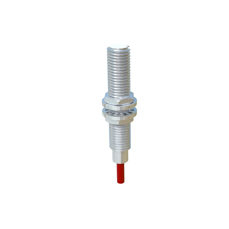
Diagnostic indicators are a small but vital visual feature. Most modern sensors incorporate an LED status light, often embedded in the housing or behind a translucent window. A steady or blinking green LED typically indicates power and normal operation, while a yellow or red LED might signal output activation, overload, or a fault condition. This visual feedback is indispensable for rapid troubleshooting on the factory floor.
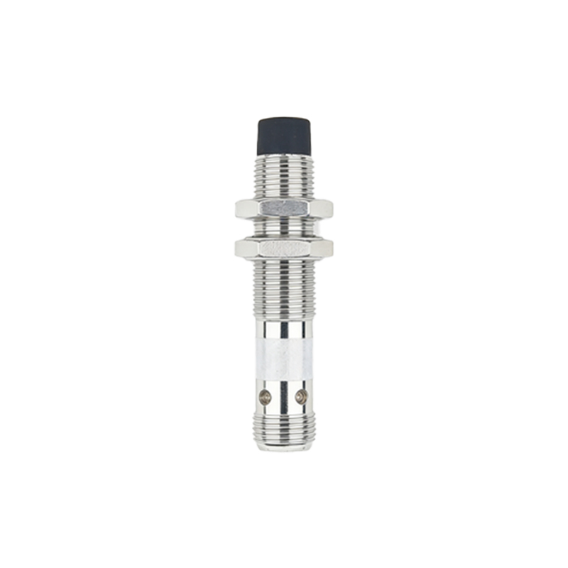
In conclusion, a thorough examination of proximity sensor real images transcends simple identification. It bridges the gap between schematic symbols and their physical implementation, revealing design choices for environmental resilience, electrical interfacing, and user feedback. For the practicing engineer, this visual literacy is essential for optimal selection, correct installation, and efficient maintenance, ensuring reliable performance in demanding automation systems where precision and uptime are non-negotiable.