Laser distance sensors have become indispensable tools in modern industrial automation, offering high-precision, non-contact measurement capabilities. As an experienced electrical engineer, I recently conducted a detailed teardown of a typical industrial-grade laser triangulation sensor to explore its internal architecture and operational principles. This article provides a step-by-step breakdown of the disassembly process, component analysis, and insights into the sensor's design and functionality.
The sensor model examined is a widely used unit with a measurement range of 50–500 mm and an accuracy of ±0.1% of full scale. Externally, it features a rugged aluminum housing rated IP67 for dust and water resistance, with an integrated M12 connector for power and data communication. The first step in disassembly involved removing four Torx screws securing the front cover. Beneath the cover, a protective glass window shields the internal optics from contaminants. Carefully prying off the window revealed the laser emitter assembly, consisting of a Class 2 laser diode operating at 650 nm wavelength, collimating optics, and a driver circuit mounted on a small PCB.
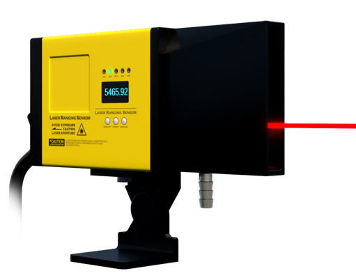
Next, the main housing was separated by unscrewing additional fasteners along the seam. Inside, the core components are arranged on a multi-layer PCB that occupies most of the internal volume. The PCB is divided into three functional sections: the laser driver and modulation circuit, the optical receiver unit, and the signal processing module. The receiver unit includes a high-sensitivity CMOS linear image sensor, positioned at a precise angle relative to the laser emitter to implement the triangulation principle. A focusing lens assembly directs the reflected laser spot onto the image sensor.
Examining the laser driver circuit, I identified a constant-current source IC designed to maintain stable laser output, coupled with a modulation circuit that pulses the laser at a high frequency to reduce ambient light interference. The image sensor is interfaced with a dedicated analog front-end (AFE) chip that amplifies and conditions the weak analog signals. The heart of the sensor is a 32-bit microcontroller (MCU) from a major semiconductor manufacturer, which handles digital signal processing, calculates distance based on the spot position on the image sensor, and manages communication protocols such as IO-Link or analog output.
The optical path is meticulously aligned using adjustable mounts secured with thread-locking adhesive, ensuring long-term stability against vibration and thermal drift. Power regulation is handled by a compact DC-DC converter that steps down the 12–24 V supply to 3.3 V and 5 V rails for the circuits. Notably, the sensor includes temperature sensors near the laser and image sensor, with the MCU compensating for thermal effects in real-time to maintain accuracy.
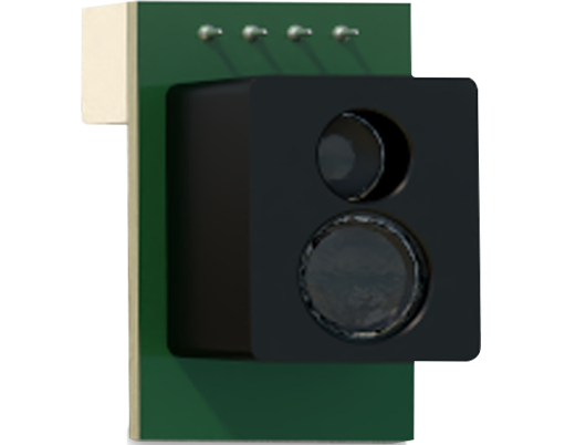
Reassembly required careful attention to seal integrity, as the O-ring gasket must be properly seated to preserve the IP rating. Throughout the teardown, the build quality and component selection reflected a design prioritizing reliability in harsh industrial environments. This analysis underscores how advanced optics, precision electronics, and robust software algorithms converge to deliver the performance expected in contemporary laser distance sensing applications.