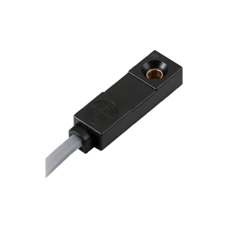
In the realm of electrical engineering and industrial automation, proximity sensors play a pivotal role in detecting the presence or absence of objects without physical contact. Their representation in schematic diagrams is standardized through specific symbols, which are crucial for clear communication among engineers, technicians, and designers worldwide. Understanding these symbols is essential for interpreting circuit layouts, designing control systems, and ensuring safety in various applications, from manufacturing lines to automotive systems.
Proximity sensors are broadly categorized based on their detection principles, such as inductive, capacitive, ultrasonic, and optical types. Each category has distinct schematic symbols that convey its function and electrical characteristics. The symbols are typically defined by international standards, including IEC (International Electrotechnical Commission) and ANSI/IEEE (American National Standards Institute/Institute of Electrical and Electronics Engineers), which promote consistency across technical documentation.
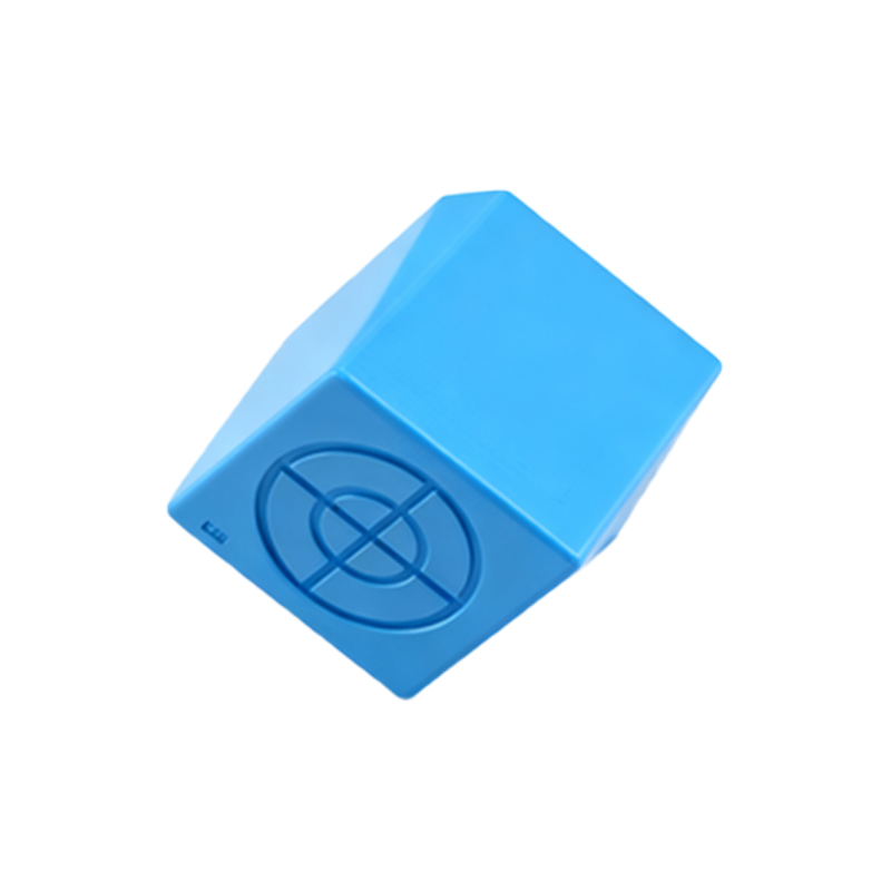
Inductive proximity sensors, used for detecting metallic objects, are represented by a square or rectangular shape with a diagonal line inside, often accompanied by a coil-like element to indicate electromagnetic induction. The symbol may include labels such as "L+" and "L-" for power supply connections, and "OUT" for the output signal, which can be either PNP (sourcing) or NPN (sinking) configurations. In schematics, these symbols are integrated into circuits to show how the sensor interfaces with controllers like PLCs (Programmable Logic Controllers) or relays.
Capacitive proximity sensors, capable of detecting both metallic and non-metallic materials, feature a similar geometric shape but with two parallel lines or a capacitor-like icon inside to signify capacitance-based operation. Their symbols often include adjustments for sensitivity, denoted by a small arrow or knob representation. Engineers must note the grounding requirements in the schematic to prevent false triggers due to environmental factors.
Ultrasonic sensors, which use sound waves for detection, are depicted with a symbol resembling a loudspeaker or transducer, sometimes with wave arcs emanating from it. This symbol highlights the emitter and receiver components, essential for distance measurement applications. In wiring diagrams, connections for power, ground, and analog/digital outputs are clearly marked to facilitate installation.
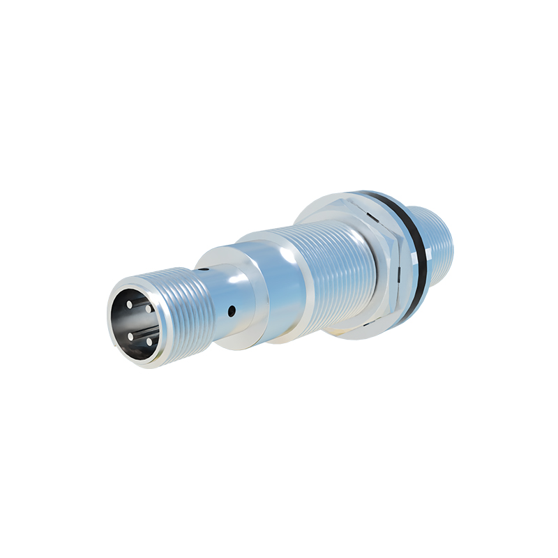
Optical sensors, including infrared and laser types, are shown with a diode-like symbol for the emitter (often an LED) and a phototransistor or photodiode for the receiver, enclosed in a unified shape. Arrows may indicate light beams, and labels specify modulation types to avoid interference. These symbols are critical in safety circuits, where alignment and response time are paramount.
When interpreting schematic symbols, engineers should refer to accompanying legends or datasheets for details like operating voltage, output type, and sensing range. Common pitfalls include misidentifying the output polarity or overlooking shielding requirements, which can lead to circuit malfunctions. Best practices involve using standardized symbol libraries in CAD (Computer-Aided Design) software and adhering to industry-specific guidelines, such as those in automotive (e.g., ISO standards) or machinery (e.g., EN standards).
In conclusion, proximity sensor schematic symbols serve as a universal language in electrical engineering, enabling efficient design and troubleshooting. Mastery of these symbols enhances collaboration, reduces errors, and supports innovation in automated systems. As technology evolves, symbols may adapt to new sensor types, but the core principles of clarity and standardization remain unchanged.