Proximity sensors are critical components in industrial automation, offering non-contact detection of metallic and non-metallic objects. Proper mounting is essential to ensure optimal performance, accuracy, and longevity. This guide illustrates common mounting methods with detailed explanations to aid engineers and technicians in installation.
Flush Mounting, also known as embeddable mounting, is the most prevalent method. The sensor is installed flush with the mounting surface, allowing it to be surrounded by metal without performance degradation. This setup provides excellent mechanical protection and is ideal for detecting objects directly in front of the sensor. Ensure the sensing face is perfectly aligned with the surface to avoid false triggers.
Non-Flush Mounting, or non-embeddable mounting, requires the sensor to be installed with a clearance around its sensing area. This method offers a longer sensing range compared to flush mounting but is sensitive to surrounding metals. Maintain the specified lateral and frontal clearance as per the datasheet to prevent interference from adjacent structures or machinery.
Side-Mounting configurations are used when direct frontal approach is not feasible. Sensors are positioned laterally to detect objects passing by. Adjust the orientation carefully to align the sensing field with the target path. Brackets or custom fixtures are often necessary to secure the sensor at the correct angle, ensuring consistent detection.

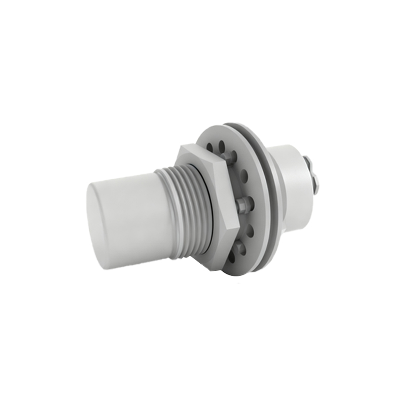
Threaded Mounting involves using the sensor’s built-in threads (common types include M8, M12, M18, and M30) to screw directly into a tapped hole. Apply appropriate torque to avoid damaging the housing. Use lock nuts or mounting nuts to prevent loosening due to vibration. This method provides a secure fit and is suitable for harsh environments.
Bracket Mounting offers flexibility for complex installations. Universal brackets, L-shaped brackets, or custom-designed holders allow sensors to be positioned in varied orientations. Ensure brackets are rigid and vibration-resistant to maintain alignment. This method is ideal for retrofitting or applications where standard mounting holes are unavailable.
DIN-Rail Mounting utilizes standard DIN rails (35mm) common in control panels. Sensors with DIN-rail adapters can be quickly snapped onto the rail, simplifying installation and maintenance in electrical enclosures. This method organizes multiple sensors neatly, facilitating wiring and inspection.
Factors influencing mounting choice include sensing range, environmental conditions (e.g., temperature, humidity, contaminants), mechanical stresses, and accessibility for maintenance. Always refer to the manufacturer’s guidelines for specific mounting distances, materials, and torque specifications. Incorrect mounting can lead to reduced sensing range, false readings, or physical damage.
In summary, selecting the appropriate mounting method enhances sensor reliability and system efficiency. Combining correct installation with regular calibration checks ensures sustained performance in demanding industrial applications. For visual reference, detailed diagrams or photos should accompany each mounting type in technical manuals.