In modern industrial automation, robotics, and consumer electronics, proximity sensors play a crucial role in detecting the presence or absence of objects without physical contact. These non-contact devices rely on electromagnetic fields, light, or sound to function. However, like any electrical component, they are susceptible to failures. One of the most common and problematic issues is an "open circuit" within the sensor or its associated wiring. This failure mode can lead to system downtime, inaccurate readings, and potential safety hazards.
An open circuit in a proximity sensor context essentially means there is a break in the electrical path that prevents current from flowing. This break can occur at several points: within the sensor's internal coil or oscillator circuit, at the wire terminations, along the cable length due to physical damage, or at the connection points to the controller (PLC) or power supply. Unlike a short circuit, which often causes dramatic failures like blown fuses, an open circuit can be more insidious, sometimes manifesting as intermittent operation or a complete failure to detect targets.
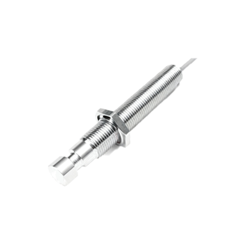
The symptoms of a proximity sensor open circuit are typically clear-cut. The most obvious sign is that the sensor stops responding entirely—it does not activate its output (whether PNP or NPN) when a target enters its sensing range. On a programmable logic controller (PLC) input module, the corresponding indicator light will remain off regardless of sensor state. In some cases, especially with AC-powered sensors or certain diagnostic circuits, a complete internal open might cause the sensor to be permanently "on." Another symptom can be erratic behavior, where the sensor works intermittently, often correlated with vibration or movement of the cable, pointing towards a broken wire.
Diagnosing an open circuit requires a systematic approach. Safety is paramount; always lock out and tag out power before performing physical inspections. The first step is a visual examination. Look for obvious signs of damage: crushed or cut cables, loose connections at the sensor housing or the terminal block, corrosion on contacts, or physical damage to the sensor body from impact. Next, using a digital multimeter (DMM) set to resistance (Ohms) or continuity mode is essential. For a two-wire AC/DC sensor, disconnect it from the circuit and measure the resistance across its two leads. A reading of infinite resistance (OL or overload) confirms an open circuit. For three-wire or four-wire DC sensors, you will need to refer to the manufacturer's datasheet to identify the internal coil or circuit pins for testing. Measuring between the supply positive (+) and the output line with the sensor powered off can sometimes reveal an open. Additionally, a voltage check with the sensor powered and connected can be revealing. For a DC sensor, if you measure full supply voltage between the output wire and the negative terminal when the sensor should be active (target present), it indicates the output transistor is not switching, which could be due to an internal open circuit preventing the sensing element from triggering it.
Common root causes of these open circuits are varied. Physical stress is a major culprit. Continuous flexing, pulling, or crushing of the cable can break the fine internal wires. Vibration in machinery can loosen screw terminals or cause internal solder joints to fatigue and crack. Environmental factors like excessive moisture ingress can lead to corrosion, breaking conductive paths. Electrical overloads, such as voltage spikes or sustained overcurrent, can burn out the internal coil or semiconductor components, creating an open. Finally, manufacturing defects, though rarer, can cause premature failure.
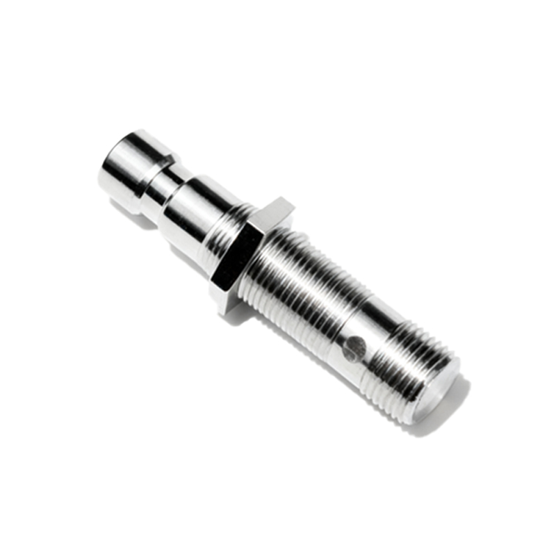
Once diagnosed, the remedy depends on the fault's location. A broken cable near the sensor often requires replacing the entire sensor if it has an integral, non-detachable cable. If the break is near the controller end, cutting the cable back and re-terminating might suffice. For sensors with connector-style or quick-disconnect cables, simply replacing the cable assembly is the fastest fix. If the open is internal to the sensor body, replacement is the only practical solution. Prevention is always better than cure. Implementing proper installation practices is key: use strain relief cable glands to prevent pull-outs, route cables away from moving parts and sharp edges, use flexible conduit in high-vibration areas, and ensure connections are tight and protected from moisture. Regularly scheduled inspections, including checking for loose connections and cable integrity, can catch problems before they lead to an open circuit failure.
In summary, an open circuit in a proximity sensor is a breakdown of its electrical continuity. By understanding its symptoms—primarily a lack of output signal—and following a logical diagnostic procedure involving visual checks and multimeter testing, maintenance personnel can quickly identify and isolate the fault. Addressing the common causes through careful installation and preventive maintenance minimizes downtime and ensures the reliable, non-contact operation that automated systems depend on.