In the intricate world of industrial automation and machine design, small proximity switch sensors are the unsung heroes of precision and reliability. While datasheets provide critical specifications, a detailed visual examination of these components offers invaluable, practical insights that transcend numerical data. This guide delves into the world of small proximity switch sensor images, interpreting their physical characteristics, installation nuances, and application contexts to empower engineers in selection and implementation.
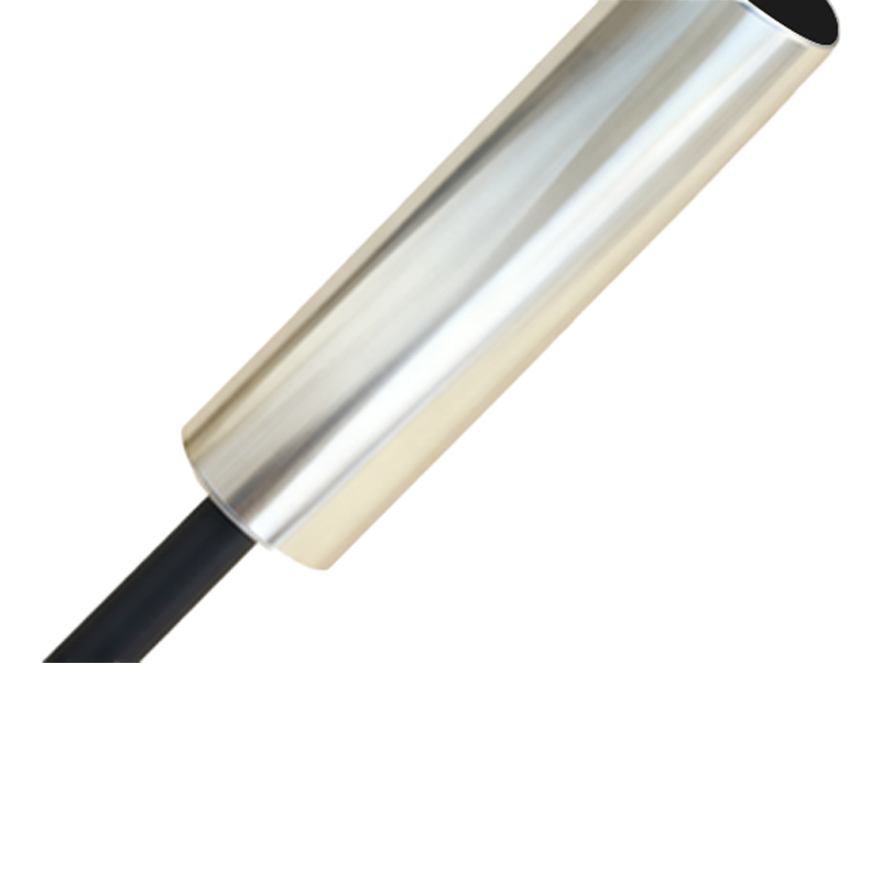
A high-resolution image of a typical cylindrical inductive proximity sensor, perhaps an M8 or M12 form factor, reveals more than just a metal barrel. The housing material, often nickel-plated brass or stainless steel, indicates the sensor's resilience to environmental factors like coolants or washdowns. The precise machining of the threads speaks to manufacturing quality and ensures a secure, vibration-resistant mount. A close-up of the sensing face, usually a polymer cap, shows its texture and recess level. A flush-mounted or non-flush design is visually apparent; a non-flush sensor has the sensing coil set back, allowing for side-by-side installation without mutual interference, a crucial detail often confirmed through imagery before layout finalization.
Contrast this with an image of a miniature rectangular or block-style proximity switch. Here, the focus shifts to mounting brackets, cable exit options (axial or radial), and LED indicator placement. A clear image will show the status LED, typically embedded in the housing. Its color and blinking patterns, often documented in application photos, are vital for on-site diagnostics. The connector type, whether a quick-disconnect (M12 connector is ubiquitous) or a fixed cable with strain relief, is immediately identifiable. Images of sensors with built-in cable glands highlight suitability for harsh environments where ingress protection (IP67, IP69K) is paramount. Seeing the gland's design can assure an engineer of its sealing efficacy.
Wiring diagrams and connection schematics are a category of images unto themselves. A well-labeled graphic showing the brown (V+), blue (V-), and black (output) wires for a 3-wire DC sensor, or the detailed configuration of a 4-wire DC sensor with both PNP (sourcing) and NPN (sinking) outputs, is indispensable. Annotated images often include symbols for the load (e.g., a PLC input module or relay coil), clarifying the current path. For 2-wire AC/DC sensors, imagery helps distinguish them from their 3-wire counterparts, preventing costly wiring errors during panel construction.
Application photographs are perhaps the most instructive. A picture of a small capacitive proximity sensor, distinguished by its often-plastic face, mounted to detect a liquid level through a glass or plastic tank wall, instantly communicates its non-metallic target capability. An image sequence showing a small, tubular inductive sensor detecting the teeth of a gear for speed monitoring provides context for sensing range, response frequency, and required mounting clearance. Photos of sensors in robotic grippers, verifying part presence before assembly, or on conveyor lines, counting small packaged goods, demonstrate real-world scale and integration challenges. Look for images showing the sensor-target relationship: the optimal distance (the rated sensing distance, Sn), the effects of over-travel, and examples of incorrect mounting that could cause shielding or reduced range.
Furthermore, cutaway or exploded-view images are engineering treasures. They reveal internal construction: the coil winding in an inductive sensor, the oscillator circuit, the solid-state output switch, and the potting compound that protects electronics from shock and vibration. Seeing the internal components builds confidence in the device's durability and explains performance limits. Similarly, graphical representations of sensing field shapes—the standard cylindrical field of an inductive sensor versus the hemispherical field of an ultrasonic sensor—are critical images for avoiding false triggers from adjacent machinery.
In conclusion, systematically analyzing images of small proximity switches—from product close-ups and wiring guides to application photos and technical cutaways—forms a critical pillar of professional engineering practice. These visuals bridge the gap between abstract specifications and tangible installation, enabling precise selection, faultless integration, and robust troubleshooting. Always seek out high-quality, detailed imagery from manufacturer catalogs or reputable technical portals to inform your design decisions, ensuring your automated systems achieve their peak potential for efficiency and reliability.