Proximity sensors are fundamental components in modern industrial automation, providing non-contact detection of metallic and, in some cases, non-metallic objects. Their reliability is paramount for processes ranging from simple object counting to complex robotic positioning. While basic functionality checks are common, a deeper understanding of a sensor's performance often lies in analyzing its output waveform. This analysis is a critical diagnostic tool for engineers, allowing for the verification of sensor health, optimization of system timing, and troubleshooting of erratic machine behavior.
The output waveform of a proximity sensor, typically viewed on an oscilloscope, reveals the true dynamic response of the device beyond a simple "on/off" indication. For a standard DC 3-wire sensor, the waveform analysis focuses on the switching transition of the output transistor (PNP or NPN). A clean, sharp transition from the "off" state voltage (e.g., 0V for a PNP sourcing sensor, or supply voltage for an NPN sinking sensor) to the "on" state voltage (e.g., supply voltage for PNP, 0V for NPN) is ideal. The key parameters to observe are the rise time (or fall time) and the presence of noise or oscillations.
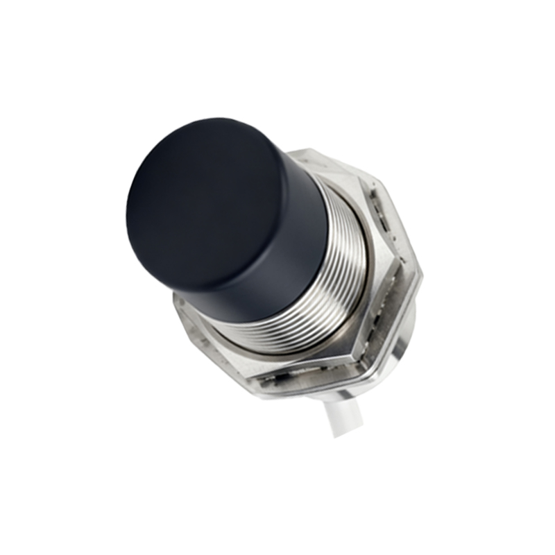
A slow rise time can indicate several issues. It may be a sign of a failing sensor where the internal circuitry is degrading. More commonly, it points to an excessive load on the sensor's output. Exceeding the specified maximum current draw can cause the output transistor to saturate poorly, leading to a sluggish transition. This slow switching can be problematic in high-speed counting applications, potentially causing missed counts or double counts if the signal lingers in an ambiguous voltage region during the sampling period of the controller.
Conversely, an excessively fast edge with pronounced ringing or overshoot at the transition point is often a symptom of electromagnetic interference (EMI) or an inductive load issue. Long, unshielded cables can act as antennas, picking up noise from nearby motors, variable frequency drives (VFDs), or welding equipment. This noise can couple onto the sensor's output line, manifesting as high-frequency oscillations on the waveform. Severe ringing can cause false triggering in the PLC or counter input, which typically have Schmitt-trigger logic designed to reject noise but have their limits. Adding a ferrite core to the cable or using shielded cable grounded at only one end are standard mitigation techniques.
The stability of the "on" and "off" plateau voltages is another crucial aspect. The "on" state voltage should be close to the supply rail (minus a small transistor saturation voltage, typically 0.1-0.5V). A significantly dropped "on" voltage under load suggests the sensor is struggling to supply the required current, potentially due to internal resistance or an overload. The "off" state should be a clean, flat line at the expected voltage. Noise on the "off" state, especially if it approaches the input threshold of the receiving device, is a prime suspect for random, unexplained triggering events.
For analog output proximity sensors, which provide a voltage or current proportional to distance, waveform analysis takes a different form. Here, the focus is on linearity, resolution, and noise. The output should be a smooth DC level that changes steadily with target movement. Any stepping, jitter, or sudden drops in the signal indicates poor resolution, internal noise, or a fault. Using an oscilloscope, one can also command a rapid, repetitive movement of the target to see if the analog output can track the motion smoothly or if it exhibits lag or instability.
In practice, waveform analysis is employed in several scenarios. During commissioning, it verifies that sensors are installed correctly and interacting properly with the load and controller. When a machine exhibits intermittent faults, connecting a scope to a suspect sensor during operation can capture transient events that a multimeter would miss. For predictive maintenance, periodic waveform checks can track the gradual degradation of a sensor's switching speed, allowing for replacement before a catastrophic failure causes downtime.
Understanding the expected waveform for a specific sensor type and application is the first step. Always refer to the manufacturer's datasheet, which may provide typical response time specifications. When analyzing, ensure the oscilloscope is properly grounded and use a low-capacitance probe to avoid distorting the signal. By mastering proximity sensor waveform analysis, engineers move from simply replacing components to truly understanding system interactions, leading to more robust, reliable, and efficient industrial automation systems.