In the realm of industrial automation, proximity sensors are indispensable components, providing non-contact detection of metallic and, in some cases, non-metallic objects. A critical parameter often scrutinized by electrical engineers and system designers is the switch-on current, also known as the inrush or start-up current. This article delves into the technical nuances of this parameter, its implications for circuit design, and best practices for ensuring reliable sensor operation.
The switch-on current refers to the momentary surge of electrical current that flows through a proximity sensor at the instant power is applied. This phenomenon is not unique to sensors; it is common in many inductive and capacitive loads. In the case of inductive proximity sensors, which are the most prevalent type for metal detection, the primary cause is the need to magnetize the sensor's internal ferrite core and establish the oscillating electromagnetic field. The initial state requires a higher current to overcome the inherent inductance and charge internal capacitors before the sensor settles into its steady-state quiescent current.
The magnitude of the switch-on current is typically several times higher than the normal operating current. For a standard 3-wire DC sensor with an operating current of 200mA, the inrush current might peak between 600mA to 1A, albeit for a very short duration, usually measured in milliseconds. This transient peak is a crucial specification found in datasheets, often denoted as Ipeak or Iinrush.
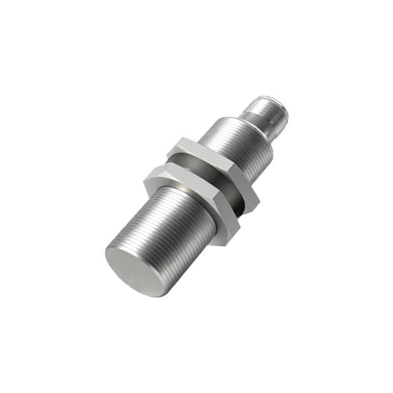
Understanding this characteristic is paramount for several reasons. Firstly, it directly impacts the selection of the power supply. A power supply must have sufficient current headroom to handle the combined inrush currents of multiple sensors switching on simultaneously, often during machine start-up, without triggering overcurrent protection or causing a voltage dip that could affect other sensitive electronics. Undersizing the power supply can lead to erratic sensor behavior or complete system failure at initialization.
Secondly, switch-on current influences the design of protection circuits and wiring. While the duration is brief, repeated high-current surges can stress electrical contacts and connectors over time. Furthermore, when integrating sensors into programmable logic controller (PLC) input modules, one must verify the module's per-point and total current specifications. Some solid-state PLC inputs have very low steady-state current limits but may be damaged by the initial surge if not properly accounted for. The use of inrush current limiters, such as NTC thermistors or dedicated ICs, is sometimes employed in high-density or critical applications, though most industrial-grade sensors incorporate internal circuitry to mitigate this effect.
Another consideration is the potential for electromagnetic interference (EMI). The rapid di/dt (rate of change of current) during the switch-on event can generate electrical noise, which may couple into nearby signal lines. Proper wiring practices—such as separating power and signal cables, using shielded cables for analog sensors, and ensuring good grounding—are essential to minimize this risk.
From a maintenance and troubleshooting perspective, an anomalously high or prolonged switch-on current can be an indicator of a failing sensor. Internal component degradation, such as a failing capacitor or a shorted turn in the coil, can alter the inrush profile. Measuring the current draw with a clamp meter or an oscilloscope with current probe during power-up can provide valuable diagnostic data.
Modern proximity sensor designs continue to evolve to address this challenge. Many contemporary models feature soft-start circuitry that actively controls the rate of current rise, significantly reducing the peak inrush current. This advancement not only eases the burden on the power supply but also enhances overall system reliability and longevity.
In conclusion, the switch-on current is a fundamental, yet sometimes overlooked, characteristic of proximity sensors. A thorough analysis of this parameter during the system design phase—through careful review of manufacturer datasheets, accurate load calculations, and appropriate component selection—is essential for building robust, fault-tolerant industrial automation systems. By respecting the electrical dynamics at play during those first critical milliseconds, engineers can ensure seamless sensor integration and long-term operational stability.