Proximity sensors are critical components in modern industrial automation, providing non-contact detection of metallic or non-metallic objects. When these sensors fail, they can disrupt entire production lines, leading to costly downtime. Understanding how to diagnose and repair common proximity sensor issues is an essential skill for maintenance engineers and technicians. This guide outlines a systematic approach to troubleshooting and repairing inductive, capacitive, and ultrasonic proximity sensors commonly used in manufacturing and processing environments.
Before beginning any repair, ensure safety protocols are followed: disconnect power, lock out/tag out (LOTO) the equipment, and verify the absence of voltage. Gather necessary tools, including a digital multimeter (DMM), oscilloscope (if available), sensor datasheet, and appropriate cleaning supplies.
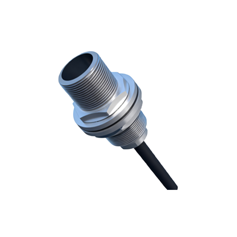
The first step in repair is accurate diagnosis. Common symptoms of a faulty proximity sensor include intermittent operation, failure to detect targets, constant activation, or no output signal. Start by visually inspecting the sensor and its surroundings. Look for physical damage such as cracks in the housing, bent or broken sensing faces, or corrosion on connectors. Check for environmental contaminants like oil, metal shavings, dust, or moisture that may interfere with sensing. Ensure the sensor is properly mounted and aligned; even a slight misalignment can cause detection failures, especially in high-precision applications.
Next, perform electrical testing. Using the DMM, measure the supply voltage at the sensor's terminals to confirm it matches the rated voltage (typically 10-30V DC for many industrial sensors). An unstable or incorrect supply voltage often mimics sensor failure. If the voltage is correct, proceed to test the output. For a three-wire DC sensor, disconnect the output wire and connect the DMM in series to measure current or in parallel to measure voltage, depending on whether it's a PNP (sourcing) or NPN (sinking) type. Actuate the sensor by bringing a target within its sensing range. A healthy sensor should switch between its on and off states cleanly. If the output is weak, erratic, or absent, the sensor's internal circuitry may be compromised.
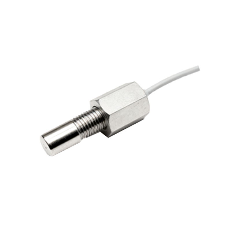
For inductive sensors, a frequent issue is reduced sensing range due to wear of the coil or oscillator circuit. If the sensor detects targets only at very close distances, internal components like the oscillator transistor or damping resistor may be degraded. Capacitive sensors can suffer from sensitivity drift, often caused by contamination on the sensing surface altering the dielectric constant. Ultrasonic sensors may experience echo problems from acoustic interference or damaged transducers.
If electrical tests indicate a fault, internal repair may be possible for some sensor models, though many modern sensors are sealed units designed for replacement. For repairable types, carefully disassemble the housing, noting the arrangement of components. Common internal failures include broken wires at terminal connections, damaged solder joints, failed output transistors, or deteriorated capacitors. Use the oscilloscope to check the oscillator waveform in inductive sensors; a distorted or low-amplitude signal suggests component failure. Replace defective components with exact or manufacturer-approved equivalents, paying attention to voltage and current ratings.
After any internal repair, recalibration is crucial. Adjust the sensitivity potentiometer (if present) according to the datasheet, using a standard target at the specified distance. Ensure the sensor triggers reliably without false positives. For capacitive sensors, recalibrate in the actual operating environment to account for background material effects.
When repair is not feasible, sensor replacement is the next step. Select a replacement with identical electrical characteristics, sensing range, housing size, and output type. Ensure the new sensor is compatible with the existing controller (PLC) input module. During installation, verify wiring according to the datasheet: brown wire to positive, blue to negative, and black (or white) as the output. Proper shielding and separation from high-voltage cables prevent electrical noise interference.
Preventive maintenance can reduce future failures. Regularly clean sensing surfaces with isopropyl alcohol and a soft cloth. Periodically check mounting stability and connector integrity. Monitor environmental conditions; excessive heat, vibration, or humidity can shorten sensor lifespan. Keep a log of sensor performance and failures to identify patterns or recurring issues.
In summary, repairing proximity sensors involves methodical diagnosis, careful electrical testing, and, when possible, component-level repair. While many sensors are now disposable, understanding their operation enables effective troubleshooting, minimizes downtime, and optimizes maintenance budgets. Always prioritize safety and consult manufacturer documentation for specific guidance.