Proximity sensors are integral components in modern industrial automation, particularly in applications involving sponge detection and handling. These sensors, often inductive or capacitive types, are designed to detect the presence or absence of sponge materials without physical contact, ensuring efficiency and preventing damage in production lines. Testing these sensors is crucial for maintaining system reliability and optimizing performance. This article provides a comprehensive guide on testing proximity sensors used for sponge detection, adhering to industry standards and best practices.
First, understand the sensor type. Inductive proximity sensors are commonly used for detecting metallic objects but can be adapted for sponges with metallic additives or foil layers. Capacitive proximity sensors are more suitable for non-metallic materials like pure sponges, as they detect changes in dielectric constant. Before testing, review the sensor's datasheet for specifications such as sensing distance, output type (PNP/NPN), voltage rating, and response time. Ensure the operating environment is free from excessive dust, moisture, or electromagnetic interference, which can affect readings.
Begin testing with a visual inspection. Check the sensor housing for cracks, corrosion, or misalignment. Verify that wiring connections are secure and undamaged, as loose connections can lead to false triggers or failures. Use a multimeter to measure voltage at the power supply terminals, confirming it matches the sensor's rated voltage (typically 10-30V DC for industrial sensors). Next, assess the output signal. For a digital output sensor, connect the output wire to a multimeter or an oscilloscope. Place a standard sponge sample within the specified sensing range. The output should switch states (e.g., from 0V to supply voltage for PNP) when the sponge is detected. Note the response time; delays beyond the datasheet value may indicate sensor degradation.
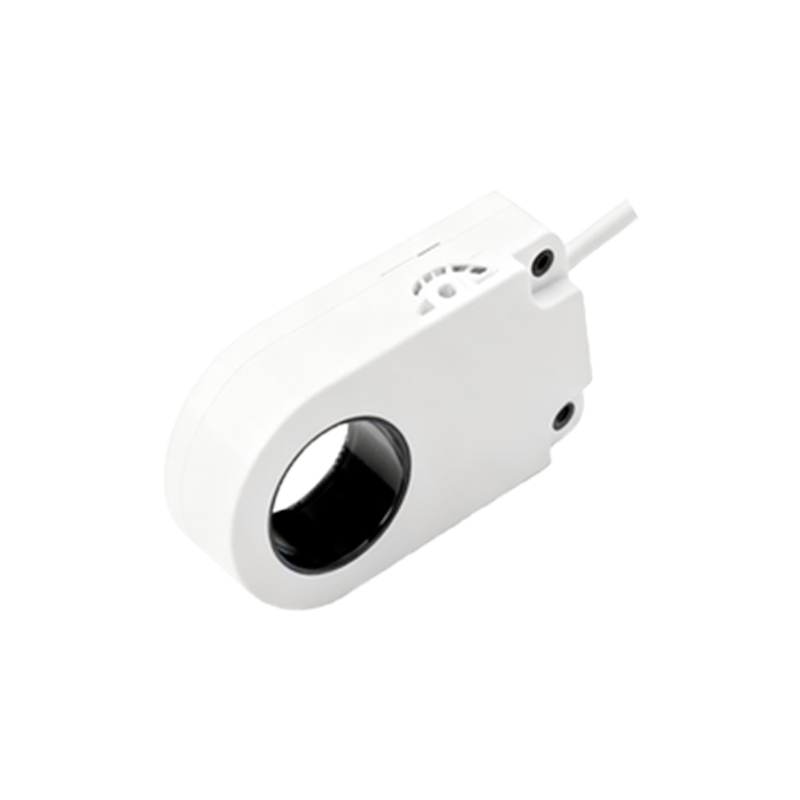
For capacitive sensors, calibration is key. Adjust the sensitivity potentiometer, if available, to fine-tune detection for sponge density and thickness. Test with varying sponge sizes and positions to ensure consistent operation. In automated systems, simulate real-world conditions by running the sensor through multiple cycles, monitoring for false positives or missed detections. Data logging tools can help track performance over time, identifying trends like drift in sensing distance.
Common issues include reduced sensing range due to material buildup on the sensor face, which requires regular cleaning with a soft cloth. Environmental factors like temperature fluctuations can also impact capacitive sensors; ensure the operating temperature stays within the specified range. If the sensor fails tests, troubleshoot by isolating it from the control system and testing with a known-good sponge sample. Replace the sensor if it consistently underperforms, as prolonged use in faulty states can disrupt production.
In summary, testing a proximity sensor for sponge detection involves a methodical approach: verify specifications, inspect physically, measure electrical signals, and simulate operational conditions. Regular maintenance and testing not only extend sensor lifespan but also enhance overall system efficiency in industries like packaging, automotive, and furniture manufacturing. By following these guidelines, engineers can ensure reliable sponge detection, minimizing downtime and maintaining high-quality standards.