--I0.0----------------------------(M0.0)-----|
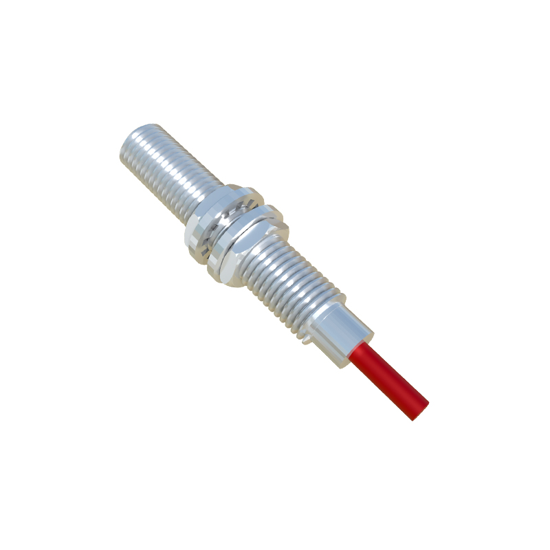
Here, I0.0 represents the digital input address assigned to the proximity sensor. M0.0 is an internal memory bit used as a flag. This simple rung copies the sensor's real-time status to an internal bit for further processing.
Network 2:
|-----M0.0-----P----------------------(T1)-----|
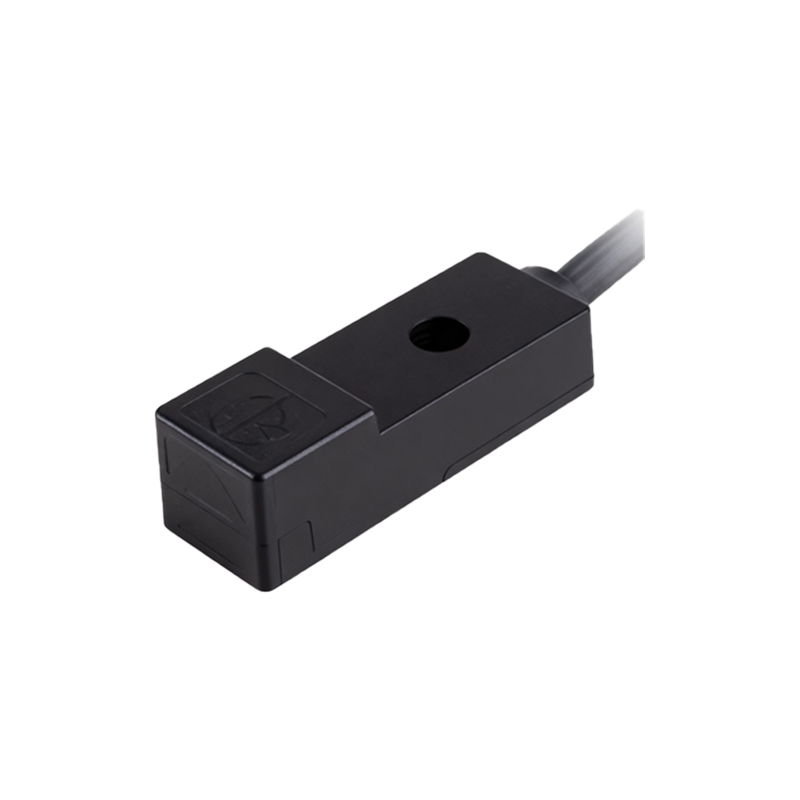
This rung uses a positive edge detection (P) instruction triggered by M0.0. The instruction detects the rising edge—the moment the sensor first sees the metallic object. Upon detection, it starts a timer (T1) configured as a TP (pulse timer). The timer's preset time (PT) is set to 500ms. This delay accounts for the conveyor's speed, ensuring the package is perfectly positioned under the diverter when activated.
Network 3:
|-----T1.Q------------------------------(Q0.0)-----|
This rung energizes the output Q0.0, which controls the solenoid valve of the pneumatic diverter arm, only when the timer's output (T1.Q) is TRUE. The diverter extends, pushing the metallic package onto the correct lane.
A crucial aspect of programming proximity sensors is parameterization and error handling. In the TIA Portal, the hardware configuration for the digital input channel connected to the sensor can be adjusted. For instance, the input delay (filter time) is set to 10ms to suppress electrical noise typical in industrial environments, preventing false triggers.
Furthermore, diagnostic logic is added. A separate timer (T2) is used as a monitoring timer. It starts when the sensor detects an object (M0.0 rises). If the sensor signal remains HIGH for an abnormally long period (e.g., 5 seconds, indicating a jammed package or sensor fault), T2 times out and sets an alarm bit (M10.0), which can trigger a visual alert on the HMI and stop the conveyor.
Network for Diagnostics:
|-----M0.0----------------------------(T2)-----|
|-----T2.Q------------------------------(M10.0)