In industrial automation and machinery, proximity sensors are critical components for non-contact detection of objects. They ensure precise positioning, count parts, and enhance safety. Over time, these sensors may fail due to environmental factors like contamination, mechanical damage, or electrical surges. Replacing a faulty proximity sensor is a fundamental maintenance task. This guide provides a systematic, safety-first approach for engineers and technicians.
1. Safety and Preparation
Before any work begins, adhere to lockout/tagout (LOTO) procedures. De-energize the entire machine or control circuit containing the sensor. Verify zero energy state using a multimeter. Gather necessary tools: appropriate wrenches or screwdrivers, a multimeter, wire strippers, crimping tools, and the replacement sensor. Crucially, ensure the new sensor matches the original specifications: sensing type (inductive, capacitive, or photoelectric), sensing distance, output type (PNP/NPN, NO/NC), voltage rating, housing size, and connection type (pre-wired, quick-disconnect, or terminal box). Consult the machine manual and sensor datasheets.
2. Removal of the Faulty Sensor
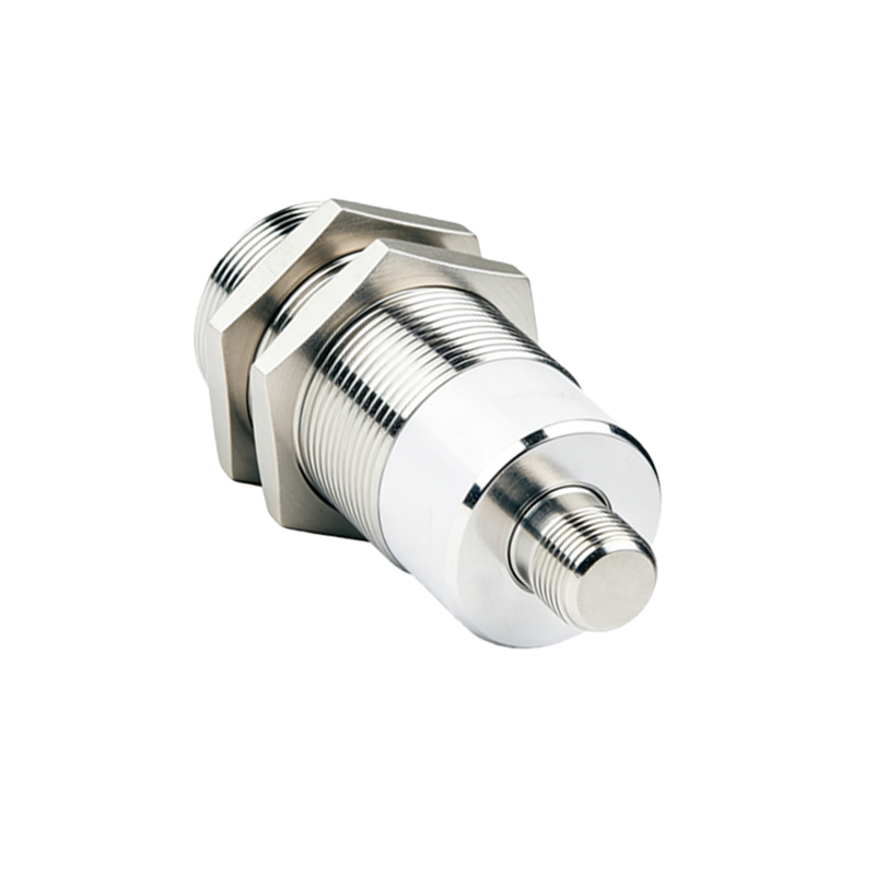
First, document the existing wiring. Take a clear photograph or sketch the wire connections, noting each wire's color and terminal number. For sensors with quick-disconnect plugs, simply unplug the connector. For hard-wired sensors, carefully label each wire with tape before disconnection. Using the correct tool, loosen the sensor's locking nut or mounting bolts. Gently unscrew or unclip the sensor from its bracket. Avoid forcing it, as the mounting thread may be corroded. Inspect the mounting area for debris or damage and clean if necessary.
3. Installation of the New Sensor
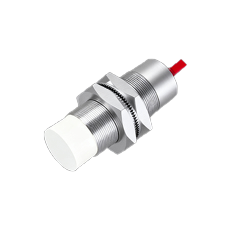
Thread the new sensor into the mounting hole or secure it to the bracket. Do not fully tighten it yet. For cylindrical sensors, hand-tighten to avoid cross-threading. If a sealing washer is present, ensure it is correctly positioned. Temporarily connect the wiring according to your documentation. For quick-disconnect systems, mate the plug firmly. For direct wiring, strip wires to the proper length, use ferrules if required, and secure them to the correct terminals with appropriate torque.
4. Alignment and Adjustment
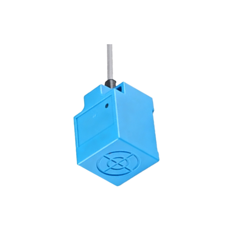
Proper alignment is vital for reliable operation. Many proximity sensors have a sensing face that must be correctly oriented toward the target. Roughly position the sensor. Re-energize the system only for testing, following your plant's safety protocols. Activate the machine to bring the target object (e.g., a metal flag) into the sensing area. Observe the sensor's indicator LED (if present). Typically, a solid or blinking LED indicates target detection. Fine-tune the sensor's position by rotating or shifting it until the indicator activates consistently at the desired point. For adjustable sensing distance sensors, refer to the datasheet for potentiometer adjustment. Once aligned, de-energize the system again and securely tighten the sensor's locking nut or bolts, ensuring the alignment does not shift.
5. Final Wiring and Functional Test
With the sensor mechanically secured, complete the final wiring connections. Ensure all terminals are tight and wires are routed away from moving parts or heat sources. Re-apply power to the system. Conduct a comprehensive functional test. Cycle the machine or process multiple times, verifying the sensor triggers consistently. Use a multimeter to check the output signal voltage matches expectations (e.g., ~24V DC for a high PNP signal, ~0V for low). Test both the presence and absence of the target. Verify the signal is correctly received by the PLC or controller by monitoring the input status on the HMI or diagnostic software.
6. Troubleshooting Common Issues
If the sensor fails to operate: Double-check power and wiring polarity. Ensure the target material, size, and approach speed are within specifications (e.g., inductive sensors require ferrous metals). Check for excessive buildup on the sensing face. Verify the sensing distance; the target may be outside the effective range. Inspect for electrical noise interference; ensure shielded cables are properly grounded. If problems persist, consult the sensor's diagnostic indicators and manual.
Best Practices: Always keep spare sensors in stock. Regularly clean sensor faces during preventive maintenance. Use conduit or protective guards in harsh environments. Document all replacements in the maintenance log, noting the date, sensor model, and any adjustments made.
Following this structured procedure ensures a reliable replacement, minimizes machine downtime, and maintains operational safety and efficiency. Remember, when in doubt, prioritize safety and consult detailed equipment documentation.