In industrial automation and machinery control, proximity switches are widely employed as non-contact speed sensors to monitor rotational or linear motion. Proper wiring of these sensors is critical for ensuring accurate speed measurement, reliable operation, and system safety. This guide provides a comprehensive overview of proximity switch speed sensor wiring, covering fundamental principles, common configurations, and best practices.
A proximity switch speed sensor typically operates on the principle of electromagnetic induction or capacitive sensing, detecting the presence or absence of a metallic target (such as a gear tooth, keyway, or bolt) without physical contact. When integrated into a speed monitoring system, the sensor generates a pulse signal corresponding to each target passage. The frequency of this pulse train is directly proportional to the rotational or linear speed, enabling precise velocity calculation by connected controllers like PLCs or frequency converters.
Wiring a proximity switch speed sensor involves three primary components: the sensor itself, a power supply, and the receiving device (e.g., counter, tachometer, or controller). Most industrial proximity switches are available in two-wire, three-wire, or four-wire configurations, with three-wire DC sensors being the most common for speed sensing applications.
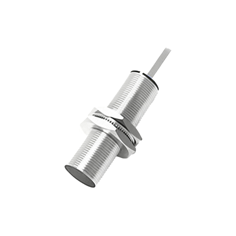
For a standard three-wire DC proximity switch:
- Brown wire: Connect to the positive terminal of the DC power supply (typically +12V to +24V DC).
- Blue wire: Connect to the negative terminal (0V or ground) of the power supply.
- Black wire: This is the signal output wire. For a normally open (NO) sensor, it provides a switched voltage output when a target is detected. Connect this wire to the high-speed input channel of a PLC, frequency counter, or other monitoring device. Ensure the receiving device is compatible with the sensor’s output type (e.g., NPN sinking or PNP sourcing).
Shielding and noise immunity are paramount in speed sensor installations. Always use shielded cables, with the shield grounded at only one end (preferably at the controller side) to prevent ground loops. Avoid routing sensor cables parallel to high-voltage power lines or near variable frequency drives (VFDs), which can induce electromagnetic interference (EMI) and cause erroneous pulse counts. Maintain proper cable lengths; excessive length can lead to signal attenuation or voltage drop, especially for two-wire sensors.
In applications involving high-speed rotation, consider the sensor’s maximum switching frequency and response time. For instance, monitoring a gear with 60 teeth rotating at 3000 RPM requires a sensor capable of handling at least 3000 pulses per second. Verify the sensor’s datasheet specifications to match the operational demands. Additionally, ensure the sensing distance and target material (e.g., steel, aluminum) are appropriate for the selected sensor type. Inductive proximity switches are suitable for ferrous metals, while capacitive sensors may be used for non-metallic materials.
When connecting to a PLC for speed calculation, programming considerations include configuring the input for high-speed counting and implementing scaling functions to convert pulse frequency to engineering units (e.g., RPM or m/s). Incorporate filtering in software to debounce signals and ignore spurious noise. For critical safety applications, such as overspeed detection, implement redundant sensor wiring or dual-channel monitoring with cross-validation.
Finally, always adhere to local electrical codes and standards (e.g., IEC, NEC) during installation. Use appropriate conduit, connectors, and strain relief to protect wiring from environmental hazards like moisture, vibration, or chemical exposure. Regularly inspect connections for corrosion or looseness, and verify signal integrity during preventive maintenance cycles. By following these wiring guidelines, engineers can ensure robust and accurate speed sensing, enhancing overall system performance and longevity.