Inductive proximity sensors are widely used in industrial automation for detecting metallic objects without physical contact. Their reliability, durability, and non-contact operation make them essential components in machinery, conveyor systems, and safety applications. Proper wiring is critical to ensure optimal performance, prevent malfunctions, and extend sensor lifespan. This guide details common wiring methods, key considerations, and practical tips for electrical engineers and technicians.
Inductive proximity sensors typically operate on DC or AC power supplies, with DC versions being more common in modern systems due to lower electrical noise and compatibility with programmable logic controllers (PLCs). Most sensors have three wires: brown (positive), blue (negative), and black (output). In two-wire configurations, the load is connected in series with the sensor, simplifying installation but requiring careful current matching. Three-wire sensors offer separate power and output lines, providing better stability and flexibility. Four-wire models include dual outputs (e.g., normally open and normally closed) for advanced control logic.
When wiring DC sensors, connect the brown wire to the positive voltage supply (typically 10-30 VDC) and the blue wire to the negative or ground. The black wire serves as the switching output, sending a signal to the controller when a metal target enters the sensing range. For AC sensors, typically with two wires, connect one wire to the live AC terminal and the other to the load. Always verify voltage ratings—mismatched voltages can cause permanent damage. Shielded cables are recommended in environments with high electromagnetic interference to prevent false triggering.
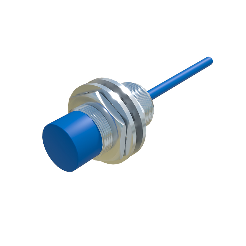
Installation practices significantly impact sensor performance. Maintain adequate clearance between sensors and metal backgrounds to avoid shielding effects. For cylindrical sensors, the sensing face should be parallel to the target surface, with the recommended sensing distance specified in datasheets (usually 0.8-15 mm). Use conduit or cable glands in harsh conditions to protect connections from moisture, dust, and vibration. Label all wires clearly and follow color-coding standards (IEC or local norms) to simplify troubleshooting.
Testing and troubleshooting are integral to wiring. Before powering up, check for short circuits or loose connections with a multimeter. After activation, verify the output indicator LED (if present) responds to metal targets. Common issues include no output signal (check power supply polarity), erratic signals (inspect for interference or unstable voltage), or reduced sensing range (clean the sensor face from contaminants). For networked systems, ensure compatibility with PLC input modules—sinking vs. sourcing configurations must align to avoid reverse current flow.
Advanced applications may involve analog output sensors (4-20 mA or 0-10 V) for distance measurement or teach-in sensors with adjustable sensing ranges. These require precise wiring per manufacturer guidelines, often with additional calibration steps. In safety-critical setups, use redundant sensors or dual-channel wiring to meet ISO 13849 standards. Regular maintenance, including periodic inspection of cable integrity and connection tightness, prevents unexpected downtime.
In summary, mastering inductive proximity sensor wiring involves understanding electrical specifications, adhering to installation best practices, and implementing robust testing procedures. By following these methods, engineers can enhance system reliability, optimize automation processes, and ensure long-term operational efficiency in diverse industrial environments.