In industrial automation and control systems, proximity sensors play a critical role in detecting the presence or absence of objects without physical contact. The reliability and accuracy of these sensors heavily depend on the performance of their signal conditioning circuits. This article delves into the design principles, key components, and practical implementation strategies for effective proximity sensor signal conditioning, tailored for electrical engineers and industry professionals.
Proximity sensors, including inductive, capacitive, and photoelectric types, generate raw signals that are often weak, noisy, or non-linear. Signal conditioning circuits are essential to amplify, filter, and convert these signals into clean, stable outputs compatible with control systems like PLCs or microcontrollers. A typical conditioning circuit comprises several stages: input protection, amplification, filtering, and output conversion.
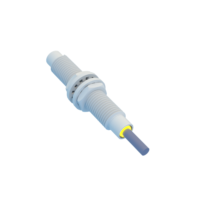
Input protection is the first line of defense, safeguarding the circuit from voltage spikes, electromagnetic interference (EMI), and reverse polarity. Components such as transient voltage suppressors (TVS), series resistors, and clamping diodes are commonly used. For inductive sensors, which detect metallic objects, protection against inductive kickback is crucial to prevent damage from back-EMF.
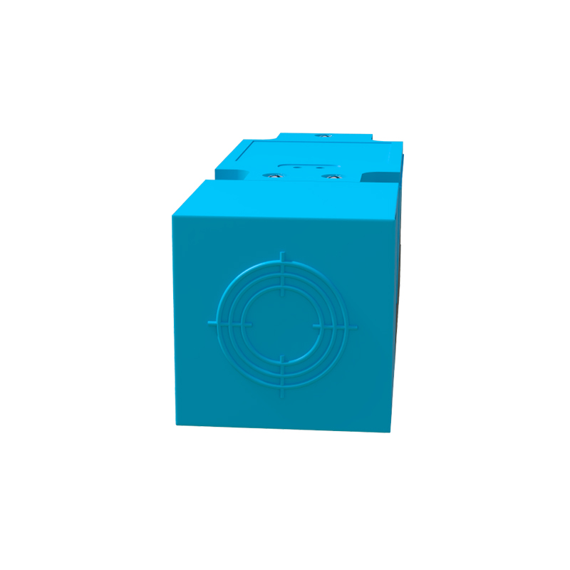
Amplification follows, where operational amplifiers (op-amps) boost the sensor's millivolt-level signals to usable ranges, typically 0-5V or 0-10V. Key considerations include gain selection, bandwidth, and noise reduction. Low-noise op-amps, like the AD620 or INA128, are preferred for high-precision applications. Gain resistors should be chosen to match the sensor's output characteristics, ensuring linear response across the detection range.
Filtering is vital to eliminate noise from industrial environments, such as motor vibrations or electrical harmonics. Passive RC filters or active filters using op-amps can be implemented. For proximity sensors, low-pass filters with cutoff frequencies slightly above the sensor's operating frequency are effective. For example, inductive sensors operating at 100kHz may use a filter with a 150kHz cutoff to attenuate higher-frequency interference while preserving signal integrity.
Output conversion adapts the conditioned signal to interface with downstream devices. This may involve analog-to-digital conversion (ADC) for digital systems or voltage-to-current conversion for 4-20mA loops. For digital outputs, comparators with hysteresis (Schmitt triggers) prevent chatter in noisy conditions, ensuring stable switching. In analog setups, precision voltage references enhance accuracy.
Practical implementation requires attention to PCB layout and component selection. Keep signal paths short to minimize parasitic capacitance and inductance. Use ground planes to reduce noise, and decoupling capacitors near ICs to stabilize power supplies. For harsh environments, conformal coating or enclosures protect against dust and moisture. Testing with oscilloscopes and spectrum analyzers helps validate performance under real-world conditions.
In summary, a well-designed signal conditioning circuit transforms raw proximity sensor data into reliable control signals. By integrating protection, amplification, filtering, and conversion stages, engineers can achieve robust operation in demanding industrial settings. Future trends include integration of smart conditioning ICs with built-in diagnostics, reducing design complexity and enhancing system adaptability.