In industrial automation and electrical control systems, proximity sensors are critical components for detecting the presence or absence of objects without physical contact. However, there are scenarios where engineers may need to short-circuit a proximity sensor—whether for testing, troubleshooting, or simulating specific conditions in a control circuit. This guide provides a detailed, professional approach to safely and effectively short-circuiting proximity sensors, adhering to industry standards and safety protocols.
Proximity sensors typically operate on low-voltage DC or AC power, with common types including inductive, capacitive, and photoelectric sensors. Short-circuiting involves creating a direct electrical connection between the sensor's output terminals or wires, effectively bypassing its normal switching function. This action can mimic the sensor's activated state, allowing engineers to verify downstream circuit behavior, such as PLC inputs, relay operations, or actuator responses.
Before attempting any short-circuit, it is essential to understand the sensor's specifications. Review the datasheet for voltage ratings, output types (e.g., NPN, PNP, or relay outputs), and wiring diagrams. For instance, a 3-wire DC sensor has power (V+), ground (V-), and output wires. Short-circuiting incorrectly—such as connecting V+ directly to V-—can cause damage, tripped breakers, or safety hazards. Always de-energize the circuit and use lockout/tagout (LOTO) procedures to prevent accidental energization during work.
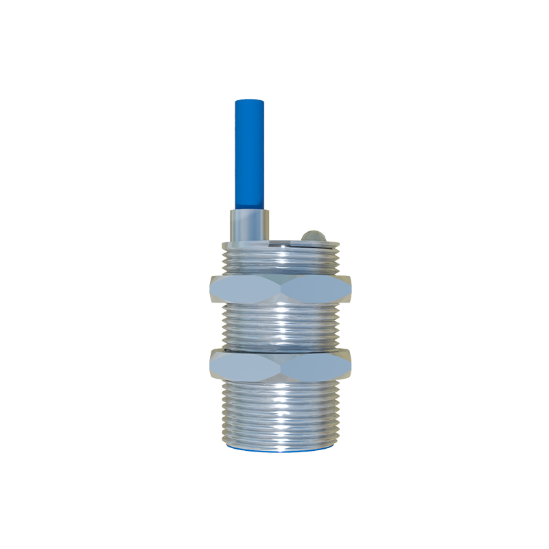
To short-circuit a proximity sensor, follow these steps:
1. Identify the Output Wires: Locate the sensor's output terminals. For a 3-wire DC sensor, the output is typically a separate wire (e.g., black or blue). For 2-wire AC/DC sensors, the output is in series with the power supply.
2. Disconnect Power: Ensure the control circuit is powered off and isolated. Use a multimeter to confirm zero voltage.
3. Create the Short: For testing purposes, use insulated jumper wires or a temporary shorting plug. Connect the output wire to the appropriate reference point—for NPN sensors (sinking output), short the output to V-; for PNP sensors (sourcing output), short the output to V+. In 2-wire sensors, short the two wires together.
4. Re-energize and Test: Restore power cautiously and observe the system response. The short should simulate sensor activation, triggering connected devices.
5. Remove the Short: After testing, disconnect power and remove the short-circuit to restore normal operation.
Safety is paramount. Avoid short-circuiting power lines directly, as this can generate excessive current, heat, or arc flashes. Use current-limiting resistors if needed for prolonged testing. Additionally, consider the sensor's design: some modern sensors have built-in protection against short-circuits, but others may be damaged by sustained shorts. Always consult manufacturer guidelines.
In troubleshooting, short-circuiting helps isolate faults. For example, if a machine fails to cycle, shorting the sensor output can determine whether the issue lies in the sensor itself or the control logic. However, this method is a diagnostic tool—not a permanent solution. For long-term bypass needs, install a maintained switch or reprogram the PLC instead.
By mastering this technique, engineers can enhance system reliability and reduce downtime. Remember to document any modifications and retest the sensor under normal conditions afterward. With proper precautions, short-circuiting proximity sensors is a valuable skill in electrical engineering, enabling efficient validation of automated systems.