Forget the pristine datasheets and the perfectly lit lab demos. After twenty years of watching inductive proximity sensors fail in steel mills, survive in chemical washdowns, and get misapplied in a thousand control panels, I’m here to talk about what really matters when you run those wires. This is not about color codes; it’s about the electrical realities that separate a robust installation from a troubleshooting nightmare.
Experience Correction: The Myth of "Standard" Wiring Practices
The textbook says: wire length is negligible, use standard gauge, and follow the manufacturer's pinout. Reality in high-noise industrial environments is a different beast. The theoretical switching frequency and repeatability you see on the spec sheet assume a perfect, low-impedance DC supply and zero electromagnetic interference (EMI). In practice, long cable runs alongside VFD motor cables act as antennas. I've documented cases where a 20-meter unshielded cable run parallel to a 50HP motor lead caused a PNP sensor to "stick" on, even with the target removed, due to induced voltage exceeding 1.5V. The fix wasn't in the programming; it was in rerouting with a minimum 30cm separation from power cables and using a shielded, twisted-pair cable with the shield grounded at the controller end only. Another critical deviation: voltage drop. A 24VDC sensor might "work" at 18V, but its sensing distance can degrade by up to 15%, and its internal oscillator becomes unstable, leading to intermittent failures. Always measure voltage at the sensor terminals under load, not at the power supply.
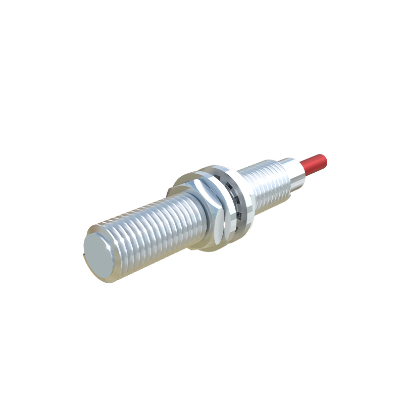
Boundary Conditions: When This Technology Fundamentally Fails
Inductive sensors are not universal detectors. Their failure modes are specific and catastrophic if ignored.
1. Ferrous Slurry and Conductive Dust Environments: In machining centers with cast iron or in mineral processing, fine conductive dust can settle on the sensor face. This creates a conductive bridge, effectively forming a "false target" that the sensor continuously detects. I've seen this shut down entire CNC lines. In these scenarios, a capacitive or ultrasonic sensor with a sealed, flush-mounted face is the only viable choice.
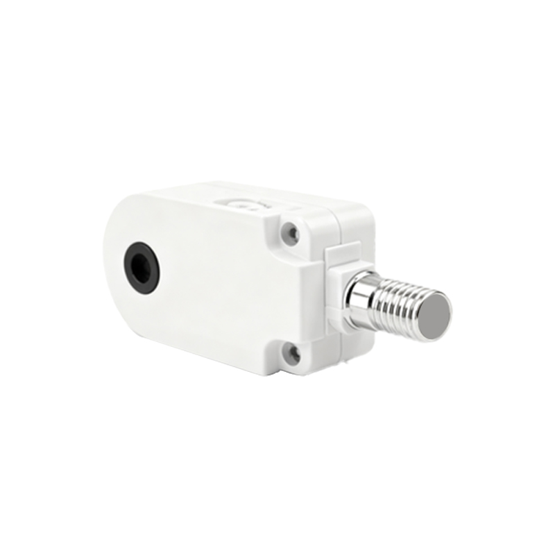
2. Extreme Temperature Gradients: A sensor rated for -25°C to 70°C might survive at a constant 70°C. But rapid cycling from ambient to 150°C (from proximity to a hot forging, for instance) will destroy the epoxy potting material through thermal fatigue within months, allowing moisture ingress. The failure is mechanical, not electronic.
3. Non-Ferrous but Electrically Conductive Targets (Aluminum, Copper): This is a classic pitfall. The sensing distance for aluminum is roughly 40% of the rated distance for steel. However, the alloy composition and temper matter drastically. A 6000-series aluminum alloy might be detected at 4mm, while a pure, annealed copper target might only be sensed at 1mm or less, making the application unreliable. If the target is a non-uniform alloy or has a passivation layer, forget consistency.
4. High-Speed Counting of Small Targets: The datasheet response frequency (e.g., 1kHz) is for a standard target. Trying to count small fasteners or thin teeth on a gear? The effective sensing field shrinks. A target must be within the nominal sensing distance long enough for the sensor's internal oscillator to shift and the output circuit to settle—this can add 0.2-0.5ms of effective dead time. At 1000 RPM on a gear with small teeth, you will miss counts.
Counter-Intuitive Conclusion: Sometimes a "Worse" Sensor is the Better Choice
The industry pushes for longer sensing ranges and faster response times. Here’s the paradox: in many high-reliability applications, you should deliberately choose a sensor with a shorter nominal range. Why? Immunity. A sensor with a 2mm range has a much more focused and intense electromagnetic field than one with an 8mm range. This makes it significantly less susceptible to false triggering from metal chips, adjacent machinery, or misaligned mounting brackets. In a tightly packed robotic cell, I consistently specify 2mm range sensors for part presence detection over 5mm ones. The installation requires more precision, but the mean time between failures (MTBF) increases by a factor of three or more. Another non-obvious insight: for DC sensors, a NPN (sinking) output is often more noise-immune in real-world panels than a PNP (sourcing) output. Many PLC input cards have better-defined and lower impedance to ground (common) than to +24V, providing a cleaner