Ultrasonic proximity sensors are widely used in industrial automation, robotics, and security systems for non-contact distance measurement. Proper wiring is crucial for ensuring accurate detection, stable performance, and system safety. This guide provides a step-by-step overview of wiring principles, common configurations, and troubleshooting tips.
Most ultrasonic sensors feature four primary terminals: power supply (Vcc and GND), trigger input, and echo output. The Vcc pin typically connects to a positive DC voltage source, ranging from 5V to 24V depending on the model. The GND pin must be linked to the system’s common ground to complete the circuit. Incorrect voltage application can lead to sensor damage or erratic readings, so always verify the manufacturer’s specifications before installation.
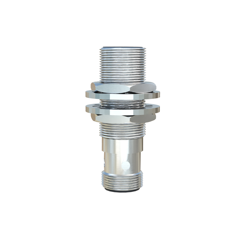
The trigger pin initiates distance measurement when receiving a pulse signal, often from a microcontroller or PLC. A common approach involves sending a 10µs high pulse to activate the sensor. The echo pin outputs a pulse proportional to the detected distance, with duration calculated based on sound wave travel time. For example, a 1ms echo pulse might correspond to approximately 17cm of distance in air.
Wiring configurations vary based on the control system. In Arduino-based projects, the trigger and echo pins connect to digital I/O ports, with a current-limiting resistor sometimes added for protection. Industrial PLC setups often require relay isolation or shielded cables to prevent electrical noise interference, especially in environments with motors or high-frequency devices. For long-distance transmission, using twisted-pair cables with proper grounding minimizes signal degradation.
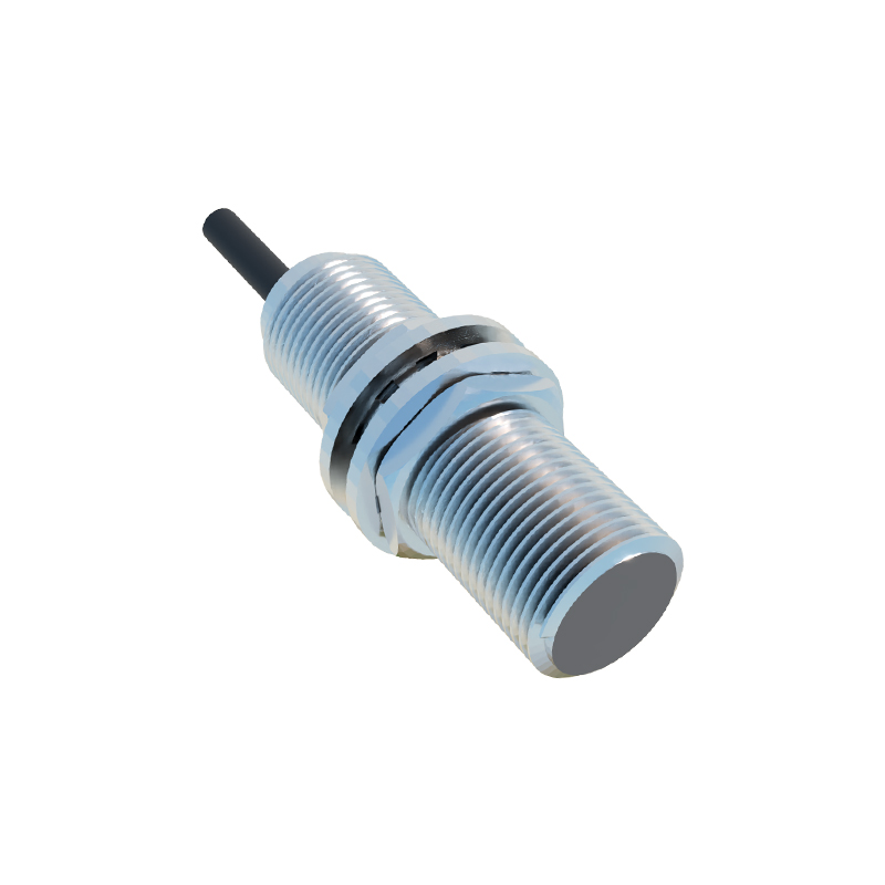
Sensor mounting also affects wiring stability. Avoid placing wires near high-voltage lines or sources of electromagnetic interference. Secure connections with crimp terminals or soldering to prevent loose contacts, which can cause intermittent failures. In outdoor applications, waterproof connectors and conduit protection are recommended to withstand moisture and temperature fluctuations.
Testing the wired system involves checking voltage levels with a multimeter and validating signal timing using an oscilloscope. If the sensor fails to respond, inspect for reversed polarity, insufficient current, or incorrect trigger pulse width. False detections may stem from acoustic interference—such as background noise or multiple sensors operating at similar frequencies—which can be mitigated by adjusting sensitivity settings or adding physical barriers between units.
Advanced setups may involve daisy-chaining multiple sensors or integrating with communication protocols like RS-485 or I2C. In such cases, follow wiring diagrams precisely, ensuring address configurations match the network topology. Always power down the system before modifying connections to avoid short circuits.
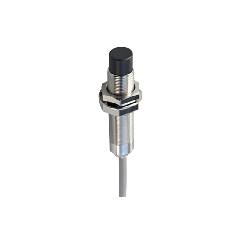
Regular maintenance includes cleaning sensor surfaces to prevent dust accumulation and periodically verifying cable integrity. Documenting wiring layouts simplifies future upgrades or repairs, reducing downtime in automated processes. By adhering to these practices, users can optimize ultrasonic sensor reliability and extend operational lifespan across diverse applications.