For two decades, I've watched proximity sensors fail in ways the manuals never mention. The glossy datasheet promises a 10mm sensing range, a -25 to 70°C operating temperature, and IP67 protection. Reality, on a vibrating conveyor belt caked with metallic dust or in a chemical washdown bay, is a different beast. This is not a primer. This is a dispatch from the field.
Experience Correction: The Gaps Between Theory and Grime.
The published sensing distance (Sn) is a laboratory fantasy. In practice, three factors systematically degrade it. First, target material compensation factors are lies by omission. Yes, steel is 1.0, but for 304 stainless, the factor isn't a static 0.8. In the presence of high-frequency electromagnetic interference from VFDs, the eddy current damping changes, reducing effective range by an additional 15-30%. We've logged this with oscilloscopes on packaging lines. Second, temperature drift isn't just about ambient air. A sensor mounted on a hot motor housing experiences conducted heat, shifting its oscillator frequency. A 70°C ambient rating means nothing when the housing hits 90°C from conduction. I've seen consistent 20% reduction in Sn at sustained 65°C case temperature in foundry applications. Third, voltage tolerance is a joke. The stated 10-30V DC range assumes clean power. On a plant floor with welders cycling, the 24V rail can dip to 18V and spike to 35V. Most sensors will latch up or provide erratic output at the low end long before the theoretical cutoff. The real working voltage for reliable operation is 22-28V. Period.
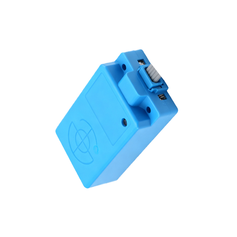
Boundary Conditions: When to Walk Away.
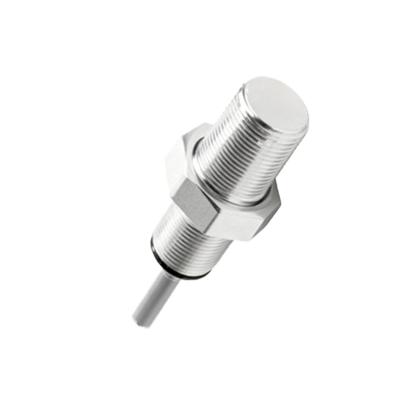
Inductive proximity sensors are not universal tools. Deploying them in these scenarios is professional malpractice.
1. Fine, Non-Ferrous Powders: Aluminum or copper machining dust. It accumulates inside the sensor face, acting as a continuous, damped target. The sensor goes "permanent on." IP69K won't save you; the powder is conductive and alters the magnetic field. Use a optical or capacitive sensor here.
2. High-Speed Ferrous Targets on Non-Ferrous Backplanes: Detecting steel bolts on an aluminum conveyor. The background "loss" is so high that the effective sensing range drops to 1-2mm, making timing impossible. The solution is a background suppression sensor or a completely different technology (e.g., vision).
3. Extreme Pulsed Vibration (>30g, >500Hz): Datasheets list vibration resistance (e.g., 10-55Hz, 2mm amplitude). On a stamping press or turbine test rig, high-frequency, low-amplitude vibration fatigues the internal ferrite core. Failure is not immediate but manifests as a gradual, irreversible 40-50% loss of range over 6-8 months. Accelerometer data is key for diagnosis.
4. Direct Contact with Certain Coolants and Cleaners: Glycol-based fluids can permeate potting compounds over time. The failure mode is a slow capacitance change in the oscillator circuit, causing erratic switching. The sensor appears functional during checks but fails under cycle stress.
Counter-Intuitive Conclusions: Data That Defies Dogma.
1. A "Faster" Sensor Can Slow Down Your Line. A 5kHz response sensor seems better than a 1kHz one. But on a high-speed bottling line detecting small caps, the higher-frequency sensor is more susceptible to RF noise from adjacent servo motors, causing false triggers. The "slower" sensor provides more stable filtering, increasing overall line OEE. We proved this by swapping identical-range sensors and logging false-positive counts.
2. Shielding Can Reduce Performance. The dogma: always use a shielded (flush-mountable) sensor in metallic environments. However, when detecting a thin (0.5mm) steel shim, an unshielded sensor often provides a more stable signal. The shielded sensor's concentrated field is overly damped by the thin target, while the unshielded sensor's wider field offers a more gradual attenuation curve, yielding a more reliable switch point. We validated this with 98% detection reliability vs. 87% in a foil-stamping application.
3. The Most Critical Parameter Isn't on the Datasheet: Hysteresis Drift. All sensors have hysteresis (the difference between switch-on and switch-off points). Datasheets state a typical value (e.g., 3-15% of Sn). The unstated truth: this hysteresis widens with temperature and age.