Understanding how to properly wire a proximity sensor is crucial for ensuring reliable operation in industrial automation, machinery, and safety systems. This guide provides a comprehensive overview of proximity sensor wiring diagrams, covering common types, connection methods, and practical considerations. Proximity sensors are non-contact devices that detect the presence or absence of an object within their sensing range. They are widely used in applications such as position sensing, object counting, and limit switching. The correct wiring is essential to avoid malfunctions, sensor damage, or system failures.
There are several types of proximity sensors, including inductive, capacitive, and ultrasonic sensors. Each type has specific wiring requirements based on its design and output configuration. Most proximity sensors have three or four wires, typically color-coded for easier identification. Common wire colors include brown for positive power supply, blue for negative or ground, black for output signal, and white for complementary output or other functions. However, it is vital to refer to the manufacturer's datasheet, as color codes can vary.
A basic three-wire DC proximity sensor wiring diagram involves connecting the brown wire to the positive terminal of the power supply (usually 10-30V DC), the blue wire to the negative or ground terminal, and the black wire to the load (such as a PLC input, relay, or indicator). The load is then connected back to the power supply to complete the circuit. For a four-wire sensor, an additional wire (often white) may provide a second output or a complementary signal. Some sensors also feature PNP (sourcing) or NPN (sinking) output configurations, which determine how the output signal is switched relative to the power supply. PNP sensors switch the positive voltage to the load, while NPN sensors switch the negative side.
When implementing a wiring diagram, consider factors like power supply voltage, current ratings, and environmental conditions. Use shielded cables in electrically noisy environments to prevent interference. Ensure proper grounding to avoid false triggers or sensor damage. For AC-powered sensors, wiring may involve connecting live and neutral wires along with the output. Always disconnect power before wiring, and verify connections with a multimeter if needed.
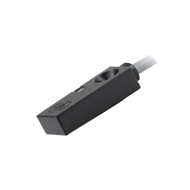
In summary, following the correct proximity sensor wiring diagram ensures optimal performance and longevity. Always consult the sensor's documentation for specific details, and adhere to local electrical codes and safety standards during installation. Proper wiring not only enhances system reliability but also minimizes downtime and maintenance costs in industrial settings.