Proper wiring is fundamental to the reliable operation of any proximity sensor. These non-contact devices, crucial for detecting the presence or absence of objects in automation and safety systems, depend entirely on correct electrical connections for accurate signal transmission. A single miswired terminal can lead to sensor failure, erratic machine behavior, or even damage to the sensor or controller. This guide outlines the core principles, standard configurations, and best practices for proximity sensor wiring, ensuring a robust and functional installation.
The process begins before any wires are connected. Always consult the manufacturer's datasheet for the specific sensor model. Critical specifications include the sensor type (inductive, capacitive, or photoelectric), the output type (NPN or PNP, sinking or sourcing), the operating voltage range (commonly 10-30V DC), and the current rating. Mismatching these parameters with the power supply and load (like a PLC input) is a primary cause of malfunction. Ensure the power supply is stable, within the sensor's voltage range, and properly grounded.
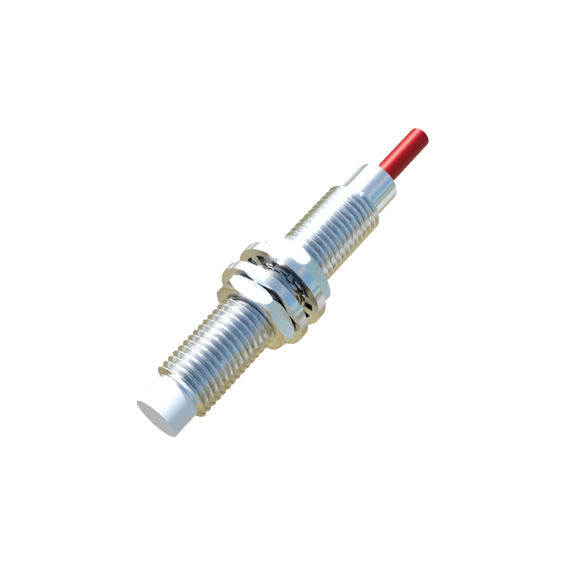
Most industrial DC proximity sensors have three wires or terminals, color-coded to a near-universal standard: Brown for the positive supply voltage (+V), Blue for the common negative or ground (0V), and Black for the output signal. A fourth wire, often White, may be present for a separate output or diagnostic function. For AC-powered sensors, typically two-wire devices, the standard is Brown for Line (L+) and Blue for Load.
Understanding the output circuit configuration—NPN vs. PNP—is the most critical step. This determines how the sensor switches the output signal relative to the common (Blue) wire. An NPN sensor, also known as a sinking sensor, switches the Negative side of the load. In its active state, it connects the Black output wire to the common Blue (0V), allowing current to sink from the load into the sensor. Conversely, a PNP sensor, or sourcing sensor, switches the Positive side. When active, it connects the Black output wire to the internal supply voltage (+V), sourcing current out to the load.
The choice between NPN and PNP is not about performance but about compatibility with the control system's input module. Many PLCs from Asia commonly use NPN-compatible (sinking) inputs, while European-designed systems often use PNP-compatible (sourcing) inputs. Attempting to connect an NPN sensor to a PNP input circuit, or vice versa, will not work. Always verify the input circuit type of your controller.
Shielded cable is highly recommended for long wire runs (over 50 feet), in environments with significant electrical noise from motors or frequency drives, or when high switching frequencies are required. The cable shield, typically a braided or foil layer, must be grounded at only one end—usually the control panel end—to prevent ground loops. Keep sensor cables separate from high-voltage power lines by at least several inches, routing them in separate conduits or cable trays if possible. Use conduit and sealed connectors (e.g., IP67 rated) for sensors in wet, dusty, or corrosive environments to protect the wire terminations.
For the actual connection, use the correct tool to strip the wire, ensuring no stray strands cause a short. Tighten terminal screws firmly to a torque specified by the connector manufacturer, as loose connections create heat and increase resistance. For quick-disconnect plugs, ensure the pin assignments match the sensor's wiring diagram. After wiring, perform a systematic check: verify power supply voltage with a multimeter, check for correct sensor output activation by introducing a target, and confirm the signal is correctly received at the controller. Implementing proper wiring practices from the start minimizes downtime, enhances system safety, and extends the operational life of both the sensors and the machinery they control.