Forget the pristine lab data. After two decades of deploying proximity sensors in foundries, mines, and chemical plants, I operate on a different set of rules. The glossy brochures and theoretical specs are a starting point, not the finish line. Here’s the unvarnished truth from the field.
Experience Correction: Where Theory Meets Grit
The advertised sensing distance is the first casualty of reality. A sensor rated for 10mm in air will not achieve 10mm in an environment with airborne oil mist or conductive dust. I've documented consistent 30-40% reductions in effective range in such conditions. The culprit is dielectric constant alteration and particulate adhesion on the active face. Temperature compensation circuits? They assume a gradual ambient shift. In a steel mill, where a sensor on a coolant line experiences rapid thermal cycling from 25°C to 90°C in minutes, I've seen hysteresis errors cause false triggers for up to 15 seconds until the internal PCB stabilizes. Rely on the "operating temperature" spec, but derate the repeatability by at least 50% at the extremes. The "IP67" or "IP69K" rating is about survival, not performance. Submerged or high-pressure washed, the housing may hold, but the sensing field is distorted by water film residue. Post-wash, a 15% fluctuation in switching point is common until the face is completely dry.
Boundary Conditions: When to Walk Away
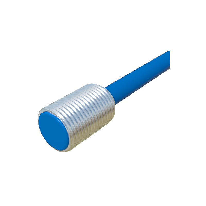
Inductive sensors and ferrous metals are a classic pair, but they fail catastrophically with hot-rolled steel. The unstable, scaling oxide layer (mill scale) creates an inconsistent air gap of varying permeability. The result isn't just inaccurate detection; it's a complete loss of signal stability. Do not use standard inductive sensors here; only specialized "immune to weld field" or "factor-1" models with extreme over-design have a chance. Another silent killer: fast-moving non-ferrous targets, like aluminum cans on a high-speed bottling line. Eddy currents need time to form. At speeds above 2 m/s, the effective sensing distance for aluminum can drop by up to 60% compared to a static test. Capacitive sensors for level detection are notoriously misapplied. Any material with a dielectric constant below 5 (like dry powders or certain granules) in a vessel with variable humidity or material coating buildup will generate unreliable data. The signal drift makes them useless for precision inventory. In high-vibration environments (>15g RMS), the internal micro-movement of the ferrite core in inductive sensors can induce a failure mode that mimics a target presence—a ghost signal. No amount of filtering in the PLC will fully solve it.
Counter-Intuitive Conclusions: Data That Defies Dogma
1. More Sensitivity Isn't Always Better. A highly sensitive capacitive sensor, touted for detecting fine materials, becomes its own worst enemy. It will detect the condensation on its own housing as reliably as the material in the silo, leading to false high-level alarms. A "less sensitive" model with a focused field often delivers higher operational reliability.
2. Shielding Can Reduce Performance. A shielded (flush-mountable) inductive sensor is preferred for metal mounting, but its field is narrower. The counter-intuitive finding: in environments with metallic swarf or chips, an unshielded sensor often performs better. The wider field, while susceptible to side interference, is less likely to be "blinded" by a small piece of debris directly in front of the core. The chip is detected and ignored, rather than blocking all sensing.
3. The "Fail-Safe" Logic Trap. Many systems are wired for fail-safe operation (sensor on = circuit closed). The intuitive conclusion is that a broken wire causes a safe shutdown. However, in DC 3-wire sensors, the most common field failure is internal leakage or minor shorting in the output transistor, not a wire break. This often creates a "frozen" ON signal, which the fail-safe circuit interprets as "all clear." The real-world safer design for critical stops often involves a pulsed watchdog circuit or dual-channel redundancy with cross-checking, contradicting the standard fail-safe wiring dogma.
The final metric isn't MTBF from a catalog; it's "Mean Time Between Unscheduled Downtime Events." That number is forged in the harsh, unpredictable reality of the plant floor, not the climate-controlled lab. Choose and apply accordingly.