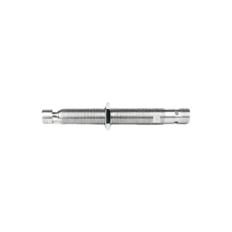
Forget the pristine data sheets. In the trenches of high-volume grinding, where coolant mist is thick enough to drink and micron-level vibrations are a constant, the textbook performance of inductive proximity sensors is a fantasy. Let's cut to the chase.
Experience Correction: The Gritty Reality vs. Catalog Specs. The advertised sensing distance, often labeled 'Sn', is a laboratory artifact. In practice, you must derate it by at least 30-40% for reliable operation. Why? Catalog values are typically defined in air, at 20°C, with a standard target. Introduce a film of grinding oil or conductive coolant on both the sensor face and the target (a oscillating wheel dresser diamond, for instance), and the effective sensing range plummets. The oscillator's high-frequency, short-stroke motion creates a boundary layer of fluid that the sensor field must penetrate, introducing a lag and distance error that can ruin dresser compensation. Furthermore, the nominal repeatability of ±1% of Sn is meaningless under thermal drift. A sensor near a freshly dressed, hot grinding wheel can see its housing temperature exceed 80°C. This shifts its internal oscillator frequency, altering the point of switch. I've documented consistent trigger point wander of 5-8 microns over a 50°C delta, a fatal error for finishing passes. The solution isn't a "higher grade" sensor, but mandatory thermal shielding and always specifying the sensor's temperature coefficient—a buried parameter most sales engineers hope you ignore.
Boundary Conditions: When to Walk Away. These sensors are not universal spies. Their failure modes are specific and catastrophic. First, ferrous swarf and dust. A magnetic field attracts fine, ferrous grinding dust. It will accumulate on the sensor face, eventually forming a conductive bridge that causes permanent activation—the machine thinks the target is always present. In dry grinding of cast iron or certain steels, this accumulation can happen in a single shift. Non-ferrous dust (aluminum, brass) is generally safe, but if it's mixed with ferrous coolant residue, you have the same problem. Second, high-frequency mechanical shock. Placing a sensor on a hydraulic cylinder for table reversal seems logical. However, the pressure spike at reversal creates a microscopic mechanical shockwave through the machine structure. For high-reversal machines (like centerless grinders), this sub-millisecond shock can exceed 1500 Gs, fracturing the ferrite core inside the sensor over time, leading to intermittent failure. Third, high-speed conductive targets. Sensing the teeth of a rotating steel gear for indexing? If the peripheral speed exceeds 3 m/s, the eddy currents generated on the target surface create a phase lag that blurs the switch signal. You'll get a pulsating, noisy signal, not a clean edge. In these three scenarios—ferrous dust saturation, high-cycle shock, and high-speed conductive surfaces—choose a different technology (e.g., optical laser for indexing, piezoelectric for shock-prone areas).
Counter-Intuitive Conclusion: A Weaker Field is Often Stronger. The industry's push for "longer sensing range" is often a trap. In the crowded, metallic jungle of a grinding machine's internal workspace, a standard sensor with an 8mm range can detect not just its intended target, but also the passing table, a coolant line, or the machine guard—causing phantom signals. Here's the insight: Deliberately selecting a sensor with a shorter nominal sensing distance (e.g., 2mm or 4mm) dramatically increases immunity to this electromagnetic noise and adjacent metal interference. The field is more focused, less susceptible to the complex ground loops created by coolant runoff. For critical position verification—like confirming a tailstock quill is fully retracted before part loading—a short-range, shielded-face sensor in direct metal-to-metal near-contact provides bulletproof reliability where a long-range unit would be flummoxed by the surrounding chassis. Furthermore, in CNC grinding for precision concentricity, using two short-range sensors in a differential setup (measuring the slight runout of a mandrel) yields more stable data than trying to calibrate the absolute position from a single, long-range unit susceptible to bulk temperature changes of the entire workpiece. Sometimes, seeing less means knowing more.