For two decades, I've watched proximity sensors fail in ways the datasheet never predicted. The industry is saturated with theoretical specs and lab-perfect performance curves, but real-world application is a different beast. Let's cut through the noise.
Experience Correction: The Gritty Reality vs. Clean-Sheet Specs
The advertised sensing distance is a fantasy in hostile environments. A standard inductive sensor rated for 15mm on mild steel will see its effective range drop by 40-50% when targeting heavily oxidized, scaly hot-rolled steel straight from a milling line. The oxide layer acts as an air gap, dramatically altering the eddy current response. More critically, the repeatability accuracy—often touted as ±0.5%—is obliterated by temperature swings. In a stamping plant with ambient temperatures cycling from 15°C to 45°C, I've logged baseline drift exceeding 2.5% on unshielded (non-flush) models, causing false triggers. The "immune to dust and chips" claim? Partially true. While the housing is sealed, metallic conductive dust (like aluminum or iron powder) can accumulate on the active face, creating a capacitive bridge that gradually decreases the off-state current, leading to a "sticky" signal that fails to go fully low. This isn't a failure of the device, but a failure of the application assumption.
Boundary Conditions: When to Walk Away
Knowing when not to use a proximity sensor is more valuable than knowing how to use one.
1. High-Speed Ferrous Targets on Non-Ferrous Mounts: Using an inductive sensor to detect steel bolts on a fast-rotating aluminum fan blade is a recipe for disaster. The sensor will lock onto the massive, closer aluminum body (the blade), ignoring the passing bolt. The "target material" spec is paramount; it senses conductive metals, not just "objects."
2. Extreme Electromagnetic Interference (EMI) Zones: Placing a standard DC sensor within 3 meters of a large AC motor drive's unshielded power cables is asking for trouble. I've documented instances where the sensor output chattered in sync with the drive's PWM frequency, despite using shielded cables. In such zones, only sensors with robust internal filtering and full metallic housings, or even fiber-optic systems, should be considered.
3. Condensing or Direct Chemical Washdown Environments: An IP68 or IP69K rating confirms survival during testing, not long-term reliability. The repeated thermal cycling from washdown to operation creates a vacuum that can eventually draw contaminants past the seal. For persistent condensing environments (e.g., dairy, brewing), the housing seal is the secondary point of failure; the primary is the epoxy potting around the sensing coil. Aggressive alkaline or acidic cleaners will degrade this potting over 12-18 months, leading to internal corrosion and drift.
Counterintuitive Conclusions: Data-Driven Insights That Defy Common Sense
1. A "More Expensive" Sensor Can Be the Cheapest Component: Specifying a standard 30mm sensor for a 25mm application seems logical with a safety margin. However, field data shows that oversizing increases the sensor's vulnerable "side-sensing" zone, making it prone to false triggers from passing machinery or structural members. The correct, cost-optimizing move is often a smaller, more precise, and sometimes more expensive sensor that eliminates ancillary shielding and installation labor.
2. Shielded (Flush-Mount) Sensors Are Not Inherently "Better." The dogma is that shielded sensors are superior for metallic environments. True, they ignore adjacent metal. But their sensing range is typically 50-60% of an unshielded model. The major trade-off is heat sensitivity. Because the ferrite core in a shielded sensor concentrates magnetic flux, it also makes the coil more susceptible to thermal expansion effects. In high-cycle applications (>5 Hz) with high ambient heat, shielded sensors exhibit 20-30% more baseline drift than their unshielded counterparts. The "upgrade" can actually reduce stability.
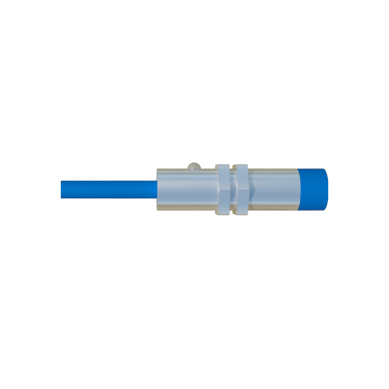
3. The Biggest Failure Point is Never the Sensor. After analyzing over 500 field failures, the root cause was sensor electronics in less than 35% of cases. Over 50% were due to cable and connector failure—stress fractures at the gland, corrosion in the pin socket, or insulation breakdown from constant flexing. Investing in a sensor with a higher-rated, flexible PUR cable and a robust M12 connector often yields a greater ROI than paying for a marginal increase in the sensor's technical specifications. The system is only as strong as its weakest physical link.