Forget the pristine data sheets. After twenty years of deploying proximity switches and magnetic sensors in steel mills, offshore platforms, and automated foundries, the real knowledge isn't found in nominal specs—it’s written in the scars of failed installations. This is a breakdown of what the catalogs don’t tell you.
Experience Correction: The Gritty Reality vs. Theoretical Specs
The advertised sensing distance is a fantasy in the real world. A sensor rated for 15mm will reliably trigger at perhaps 10-12mm in a controlled lab. Introduce ferritic dust, vibration, or temperature swings, and that window shrinks to 8mm. The critical parameter isn't the nominal sensing distance; it's the derating curve under EMI and temperature. We once tracked a batch of Hall-effect sensors failing intermittently on a CNC lathe. The culprit wasn't the chip but the inductive voltage spike from the spindle motor's braking circuit, inducing noise that the sensor's internal comparator couldn't filter. The fix wasn't a "better" sensor but a 10-cent ferrite bead on the supply line. Similarly, the "IP67" rating means nothing if a high-pressure wash blasts past the O-ring during thermal cycling. The real durability test is continuous thermal shock, not static immersion.
Boundary Conditions: Where This Technology Will Betray You
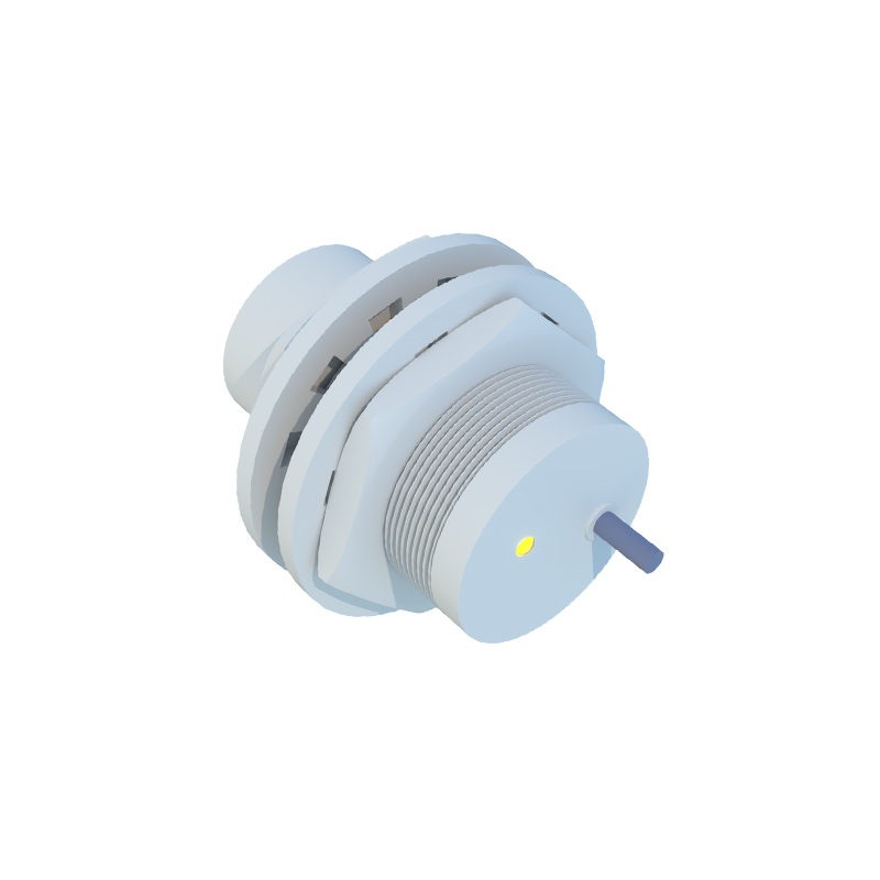
Proximity sensors have fatal blind spots. Using a standard inductive sensor near high-carbon steel (e.g., hardened tooling) is a recipe for inconsistency. The material's permeability alters the damping curve, causing premature or delayed switching. In such cases, a factor-1 alloy-specific sensor is mandatory, not optional. Magnetic sensors, particularly reed switches and even some TMR (Tunnel Magneto-Resistance) units, are catastrophically vulnerable to external stray fields. Placing them within three meters of large DC bus bars or welding equipment is an invitation for phantom signals. We documented a safety-critical door position system failing because the magnetic latch's field was distorted by the steel door frame's remanent magnetism after a fire alarm solenoid actuation. The boundary is clear: never rely on magnetic sensing in dynamically changing ferromagnetic environments or where strong AC/DC fields are present. Also, forget about any standard magnetic sensor in cryogenic or sustained high-temperature (>150°C) applications without specialized, often custom, packaging.
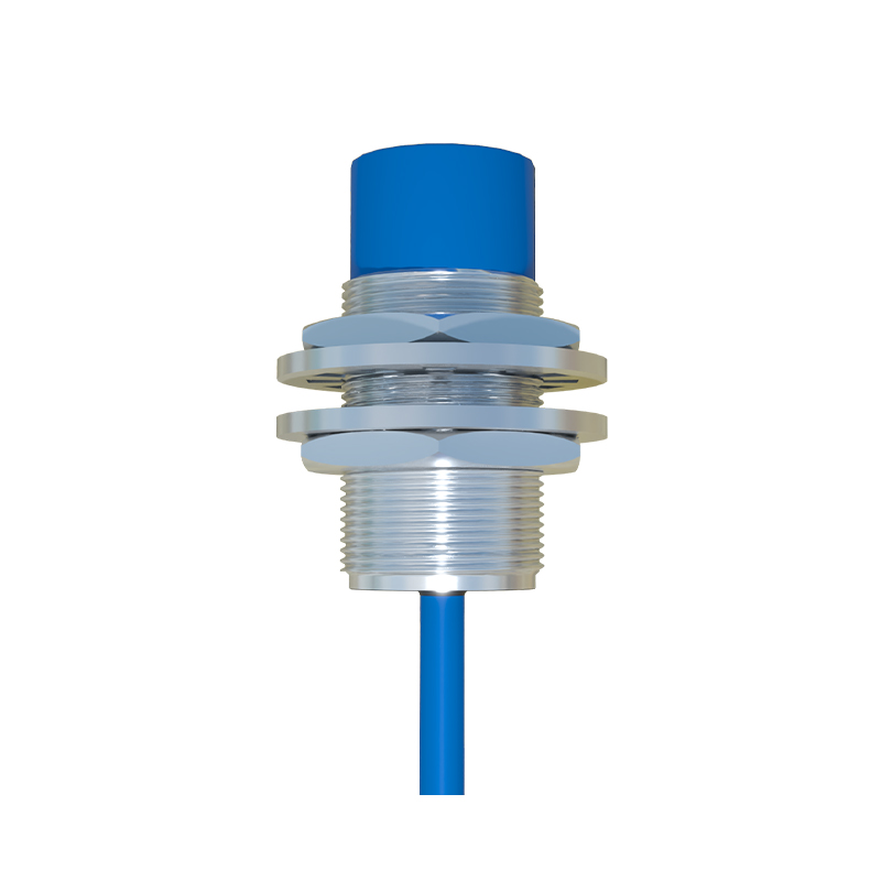
Counter-Intuitive Conclusion: Sometimes Less Sensitivity is More
The industry's push for higher sensitivity and miniaturization is often misguided. A ultra-sensitive sensor becomes a noise antenna. In high-vibration environments (e.g., stamping presses), we deliberately select sensors with a lower frequency response and a wider hysteresis gap. This prevents chatter—the deadly rapid on/off toggling that destroys contacts and PLC input modules. Data from a packaging line retrofit showed that switching from a 5kHz response sensor to a 2kHz model reduced erroneous counts by over 99%, despite the "slower" spec. Another non-intuitive insight: the most reliable mechanical mounting is often not the rigid, stainless-steel barrel. In applications with shear forces or impact risk (like material handling), a sensor with a PBT plastic housing and a flexible mounting bracket absorbs shock better, preventing internal PCB solder joint fractures—a far more common failure point than the sensing element itself. The pursuit of absolute precision in a rugged environment is a fallacy. Robustness is engineered through deliberate, informed imperfection.